Currently replacing my 65 Dart wiring. Similar to 71, but your colors are different.
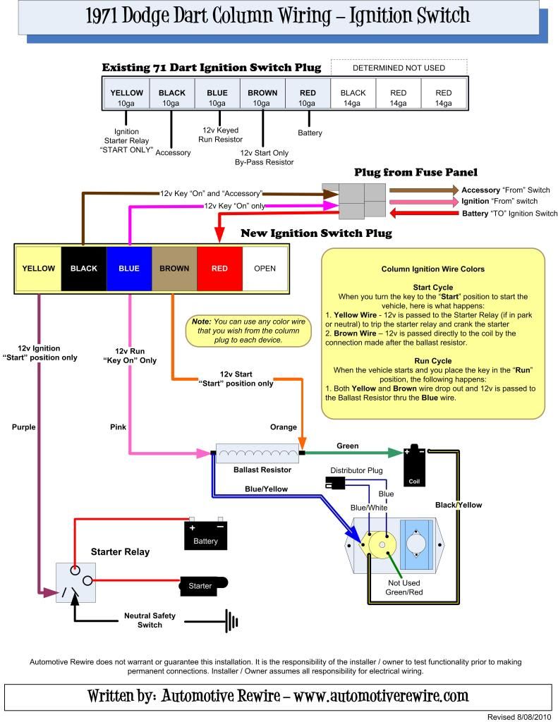
Your "ignition on" wire (pink above), which normally powers the coil, is dark blue 16 awg. It runs from Bulkhead terminal B to the ballast resistor upstream side, where it shares the spade with a smaller 18 awg dk blu wire to IGN term of the voltage regulator.
The downstream side of the ballast resistor has a 14 awg dk blu wire to coil + (grn above). It shares the terminal with a 14 awg brown wire from Bulkhead term D (org above). That wire bypasses the ballast resistor by getting direct 12 V from the ignition switch when the starter is on.
I wouldn't cut any wires if you want to keep it original. Just remove your factory ballast resistor and run extender 2 wires from the terminals to your new ballast. They are standard "spade lug" connectors. You might put some heat shrink over the connections or wrap w/ silicone tape. I wouldn't get too fancy since a later ignition you add probably won't need a ballast.
If your wires are real bad or already hacked (like mine), you might run new wires from the bulkhead housings. You can get new terminals to clip in the housing, termed "56 terminals" or "Packard 56". They were used on many GM & Mopar. Squeeze the teminal lengthwise with needle-nose pliers to compress the lock and they pull out. Be careful or the bulkhead lock tabs will break off. Even if they do, friction should hold it fine. Be glad you don't have the later design where they routed the large ammeter wires thru spades instead of the separate large lugs you have. The later ones melted the bulkhead in many cars. Also, sand and apply silicone grease.