varlo
Joe- Long Island, Oakdale
wow great info.....subscribed. I hope to pull this off as well.
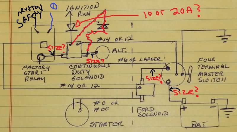
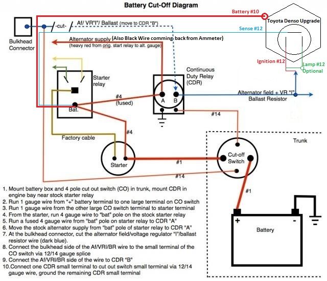
When you look at the diagrams as long as the system power is hot the car will run with the alternator.The system power is hooked to the ignition.separate the two.

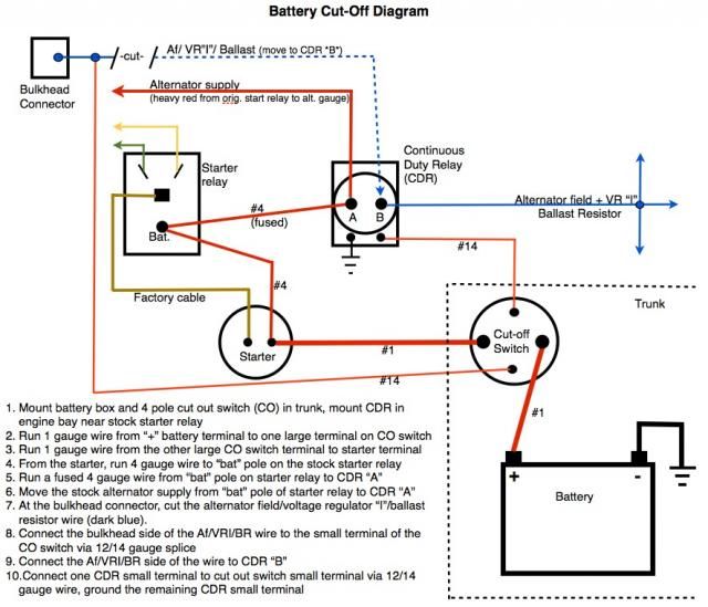
I know this is an old post, but I didn't see it addressed. You can ground the battery to the chassis at the rear, and then ground the engine to the chassis at the front. It will work. Until something isn't perfect and then you'll have hard cranking and possibly no starting.What gage wire are you going to run to your starter back to your battery?
And are you going to run just one wire, Can't you just ground it in the trunk to the frame ?.
")
I have installed several systems and to be honest the way that our mopars have the shield you wont find in many other cars. It is safe to do so. I just make sure it is also ran inside a wire loop for double security, Under the car I feel that there can be a rupture in the fuel line and with a hot wire close and sparks it just doesnt feel right. Sounds explosive.LOL


