Car only wants to run when key is still in start position

-
Put key in run position, test both side of the ballast for voltage.

If you have no voltage at either side, it's likely a wiring issue from ignition switch, through bulkhead to the ballast.
 
How to test the ignition side ...isn't all ignition side running through it... have a fluke meter... I know how to ohm and check dc voltage but did not understand what he meant by test the ignition side of the ballast

Please..............what MODEL fluke?


"Ignition side." To me, there is the "key side" or "switch side" and the "coil side."

Here is a simplified diagram of the newer "4 pin" ECU with "2 terminal" ballast from "MyMopar"

The "existing wire" is power coming IN from the ignition switch or "key." This should read withing 2-3 TENTHS of a volt at "same as battery." By the way, what you posted is NOT charging. "Charging" or normal running with system warm is about 13.8--14.2, not below 13.5, and not above 14.5

Through the ballast and to the + side of the coil..........this voltage varies a LOT. That is why it's called a "ballast." These resistors CHANGE RESISTANCE with load and temperature. With "key on" and "engine off" voltage might be as low as 4--6V depending on the coil

"Running" at idle, 8-10 or as high as 12. This ALSO will depend on the coil used. Heavier, high-ratio coils will run LOWER voltage because they draw more current

 
With the car shut off I would pull the connectors back just far enough to probe it and it read .8 and took the car down the street and back and it started sputtering and missing so shut the car off and probed again and got a reading of 1 ohm
Just as an FYI.....as noted, you have to disconnect one side of the ballast to read the resistance; with both wires connected, you are measuring the whole car's ignition system.....that's a meaningless test. And the difference between .8 and 1 ohm is insignificant and is mostly due to the contact resistance of the probes, not the device that you are measuring....
 
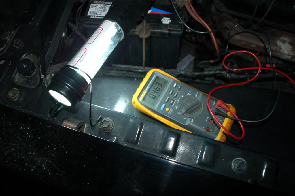
That is LOW LOW LOW!!!!!!!!!!!!!!!!!!

Compare that 9.34 to battery voltage

That is, what IS battery voltage? If the battery is dead, ????

In other words the "high side" of the ballast should be within 2-3 tenths of one volt as "same as battery."

Here is your current path

Read this, but mostly look at the diagram:

http://www.madelectrical.com/electricaltech/amp-gauges.shtml

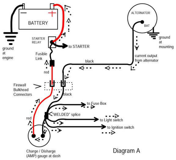
The simplified diagram from the above page:

Follow along. Start at the battery, to the stud on the starter relay, follow the FUSIBLE LINK along the RED wire through the bulkhead connector.

From there we go to the ammeter, through the ammeter, and out on the BLACK ammeter wire. Notice that we come to the "welded splice." See where it says "to ignition switch?"

What is NOT shown is now we continue on from the splice, to the IGNITION SWITCH CONNECTOR, the switch, through it, BACK OUT the switch connector (on the ignition run line, or IGN1, dark blue) and BACK OUT through the bulkhead connector

Now that we are back through the bulkhead connector, we feed any underhood loads, in your case, the ballast resistor and the voltage regulator.

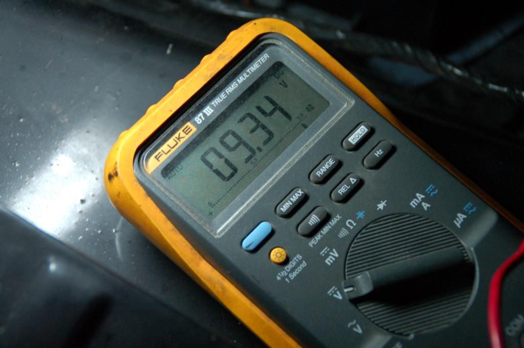
WHY IS THIS ONLY 9 VOLTS?

Because, somewhere in the above circuit path, you have a BAD CONNECTION

The bulkhead connector terminals are probably the no1 cause

About next on the list is the ignition switch connector, or the switch itself.

Next might be troubles at the ammeter, the connections, or inside the ammeter itself.

Last, rare, but this HAS happened, is sometimes, the welded splice has failed.

You need to backtrack, LEARN to test for voltage drop, and FIND the trouble.


amp-ga18.jpg


??HOW?? do you find this??

You learn to read diagrams. Download a factory manual. It's "just like" a road map. You have a GREAT multimeter, hell, it might be better than my old Flukes, which are more than 15 years old

FIRST!!!! You MUST have the circuit under test UNDER LOAD to find voltage drop. This is especially important if you have a breaker points system, because when the points are open, with engine not running, but with key "on" there is only the alternator field through the regulator.

HOW?? to simulate a load??

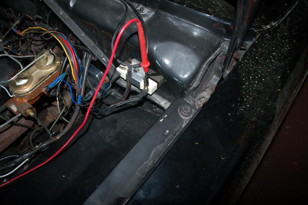
One way is to pick the "high" side of the ballast, and hook a load to it for testing.

SO!!! find yourself something like an old headlight that still works, "rig" some (heavy) clip leads to the lamp, and hook it to the same place as your VR IGN terminal.

Now you can unhook the ballast and "not" burn up the coil, ballast, or points as you test

So with your load (lamp) hooked up, and key "in run" you can start to look for the trouble.

THINK in your mind, "the circuit path." Just like a road map.

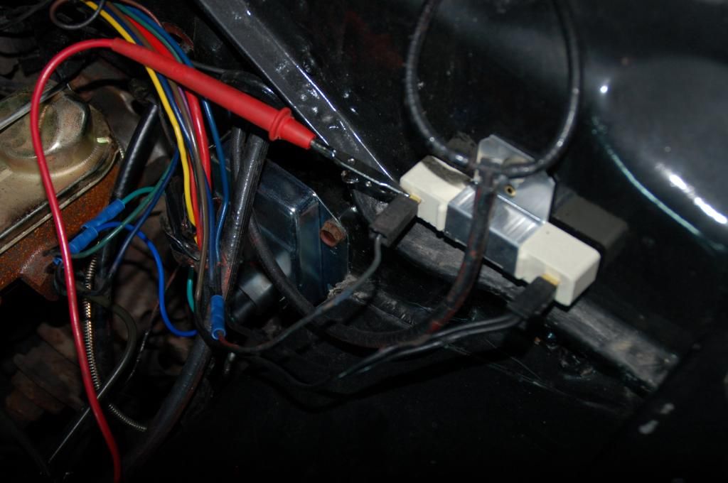
FIND the wire where "ignition run" (dark blue) comes through the bulkhead. PROBE that and compare the voltage to the BATTERY voltage

WIGGLE the wire terminal in the bulkhead. V goes up? Changes? good indication you might have found part of the problem

Go inside the car. Probe the same terminal from INSIDE the car. Is the voltage higher than the last test?

You are on the right track.

"Jump" to the IGN switch. Pull it out, hang it down, so you can get to it. Probe the battery (big black) wire and compare that reading to "right at the battery" Is the voltage close to the same? Much lower?

That would indicate a problem in the RED wire coming through the bulkhead, or the ammeter.

Now compare voltage at the big BLACK going into the IGN switch, and the "dark blue" ignition run.

Are these voltages different? How much? "Wiggle" the switch connector. Any change?

Wiggle the key in the switch........any change?

This is exactly like driving down a highway, you go here, you stop for gas, you go further, you fix a flat tire, and so on. You change highways. You turn off onto this little road. Follow the map
 
Yeah sorry I told ya the wrong fluke model lol...I'll start tracing down wires tomorrow
 
ok ... so decided to check around while i was working on some other things and have the negative battery cable off the car, I grab my probes and check the voltage on the battery side of the coil with + going to the battery side of the ballast and the - side goin on the battery stud and I got the same voltage as what was shown when I checked voltage on the battery...so i reconnect the ground strap to the post and recheck voltage... I have a drop in the voltage with the ground strap attatched to the battery and with it off the battery I get identical voltage readings
 
Jake,
I am lost on your last post. You need to explain clearer. What is "battery side of the ballast"? There is an IGN1 side (upstream) and an IGN2 side (downstream). Not sure what having BATT- disconnected lets you infer. Not sure what "same as last time" means.

Changing to HEI and getting rid of the ballast greatly simplifies the ignition. For $45 you can get a new distributor w/ simple hookup, if you have a small block. I don't see where you bothered to tell us what engine, year, or mod.s you have.
 
Jake, confirm that this is what you are saying: He has the - lead of the meter to the battery - stud and then puts the + lead of the meter to the ballast connection to the coil with the key in the RUN position and gets a voltage reading that is the same as the battery by itself. This would make sesne, since the battery + would be connected to the coil, ballast, etc. BUT it is not drawing any current since the battery - lead is off and so there will be no voltage drops.

So this is a meaningless measurement, Jake (if I interpet your words correctly). The only valid, useful measurements are with the power source (battery) and load (ignition circuit) connected.

With the system connected, make voltage measurements at the following points in the ignition cirucit with the meter's - lead to the battery - , with the key in the run position, and plaase report them here with these labels (so we can all keep track of them):
Battery +
Large stud on starter relay
Igntion 1 feed to ballast (2 dark blue wires end)
Ballast connection to coil + (brown wire end)

This is the first steps in what 67dart273 is aksing you to do.
 
sigh...this electrical issue is wearing my brain out... between the 12hr days in the sweat shop or sweating while working on this thing I am about to whits end...here it is nm9stheham
Battery-12.2
Start relay-12.05
Ign 1 feed to ballast-4.5
Ballast to coil-9.07
 
I just want to tell everyone thanks for all your guys help on trying to figure this out...wish someone more elec. savvy was closer to help me but unfortunately not!
 
sigh...this electrical issue is wearing my brain out... between the 12hr days in the sweat shop or sweating while working on this thing I am about to whits end...here it is nm9stheham
Battery-12.2
Start relay-12.05
Ign 1 feed to ballast-4.5
Ballast to coil-9.07

You have the last two reversed, unless I'm confused.

You need to be clearer and more specific about what you are doing

This is with the key in the "run" position and not the start position?

If so, you have several volts drop between the battery and ballast, as I said earlier in post 33
 
What Del is saying above seems correct...the voltages on the last 2 seem to be reversed. Can you verify that? But the good news is that you look to be taking accurate voltage readings; that is a big help to everyone.

The main point is that the 9.04v at the ign1 feed to the ballast is significantly too low; it should be close to battery voltage when the key is in RUN. This is likely either caused by either:
1. The wiring between the igntion switch 1 and the ballast is faulty; this is often at the bulkhead connector. Trace back the dark blue wiring from the ballast.
2. The ignition switch or it's connector are crapping out.
3. The voltage path into the ignition switch is crapping out; that is shown on the schematic that Del (67Dart273) showed in post #33.
4. Perhaps (but least likely) the fusible link is partially failed.

Try the following test to simultate a good ignition siwtch connection to the ballast and to verify that the low voltage feed to the ballast from ign1 is the problem. Attach a jumper directly from the battery + to the blue wire lead going to the ballast. Then start the car and see if it runs when you release the key form START to RUN. DO this just long enough to run this test. If the car runs good jumpered that way, then indeed the ign1 feed to the ballast is the issue and you can focus on that. If it does NOT run with that test, then the problem lies elsewhere past the ballast, in the coil or distributor area.
 
so lets say I crimped the ammeter wires together and didnt rewire from the Alt to the starter relay!?!? will that cause any damage?
 
so lets say I crimped the ammeter wires together and didnt rewire from the Alt to the starter relay!?!? will that cause any damage?

It seems to me you are jumping around here with no direction

Go read this article. You might have to read it more than once. It fully explains the problems with the bulkhead connector

http://www.madelectrical.com/electricaltech/amp-gauges.shtml

Then go read my post no33 AGAIN.

This current path follows just like a road map. There are chuckholes and speed traps along the way
 
ok, no here goes...the original fusible link that is leading from starter relay to the bulk head connector is no more, when i purchased this car it had a blade fuse installed in that spot... with that being said I have pulled all bulkhead connectors in the engine bay, none of them are burnt or show signs of melting, however when the key is in the run position the wiring around this blade fuse is severely hot.. but while the inst. cluster is out I feel the wires of where the ammeter hooked to the cluster and dont feel any heat at that connection.. so could the wiring of where this blade fuse came in be faulty?.. whats creating all the heat in the wire at that point?.. I havent seen any major voltage change by wiggling any wires in the bulkhead or under the dash area..so the only reason I seem to be jumping around alot is that nothing is making any sense as to why the voltage would be low or why its creating so much heat on just a 8" span of wire..corrosion resistance possibly..I am utterly at a loss sorry for many confusing posts to ya guys...its helping you just cant tell
 
PROBABLY the reason it's hot is that you have a BAD CONNECTION right there somewhere, in the bulkhead connector, or in the fuse holder.


READ POST 28 and

READ POST 33
 
ok, no here goes...the original fusible link that is leading from starter relay to the bulk head connector is no more, when i purchased this car it had a blade fuse installed in that spot... with that being said I have pulled all bulkhead connectors in the engine bay, none of them are burnt or show signs of melting, however when the key is in the run position the wiring around this blade fuse is severely hot.. but while the inst. cluster is out I feel the wires of where the ammeter hooked to the cluster and dont feel any heat at that connection.. so could the wiring of where this blade fuse came in be faulty?.. whats creating all the heat in the wire at that point?.. I havent seen any major voltage change by wiggling any wires in the bulkhead or under the dash area..so the only reason I seem to be jumping around alot is that nothing is making any sense as to why the voltage would be low or why its creating so much heat on just a 8" span of wire..corrosion resistance possibly..I am utterly at a loss sorry for many confusing posts to ya guys...its helping you just cant tell
That is a good find. A big problem is no doubt the blade fuse holder; most of the ones from the auto store cannot handle large amounts of current reliably; it could have corrosion anywhere inside. A LOT of current flows back and forth through the line that WAS a fusible link.

Get rid of that fuse and holder; being hot says it is dropping a lot of voltage. See if you can find a fusible link to put back in there. The new link need to have a crimped connector to the start relay. Not sure what you have to connect at the firewall end but get rid of any butt connectors that were put in that line, even if you have to crimp in a new butt connector.

Do this first, then re-start troubleshooting.
 
ok..been doing some looking around here and there.. I have a complete color coded wiring diagram for the car, I took the chopped up wiring out from bulkhead connector in the middle marked on my diagram "J" from the back of the connector, pulled the spade out and cleaned it up and rewired for a little better connection for the time being so I can keep looking with voltage going to the rest of the car, just replaced the ignition switch and as I am inspecting the wiring harness with the cluster out I can hear the ballast sizzling..sigh..I am not getting any better rereading posts 28 or 33 or #485763435367... I cant get the voltage to change much and fear I have already roasted my 3rd ballast resistor..so as it sits.. I have crimped and soldered the ammeter wires, not yet ran the independent wire from the alt to the starter relay, replaced Ign switch in the column with new, replaced alternator, replaced VR and started tracing down the wires from battery to starter relay to bulkhead connector J...so findings so far I am getting identical battery voltage from batt to start relay...same voltage to the spade connector on the bulkhead..checked the welded splice in the harness, its not melted anything and has original "grip" tape wrapping.. bulkhead connectors seem to have no signs of melting or hardly any corrosion.. so I am getting frustrated chasing the ghost here..
 
There is no "ghost." Follow the wiring diagram. It's just exactly like a road map. You go north in hiway 21 to the junction at "Whatever" and go south to etc

For wiring diagrams re: this discussion, you need to go by the FACTORY manual, so that anyone discussing this knows what "we both" (all) are referring to. Download a factory manual if you have not:

http://www.forabodiesonly.com/mopar/showthread.php?p=1970088617

more here

http://www.mymopar.com/index.php?pid=31

This is why post 33 is so important..........it outlines the path, the roadway the circuit follows FROM THE BATTERY to the IGNITION

The ROAD IS

Battery.............fuse link............through the bulkhead............to the ammeter,.............through the ammeter.........out the black ammeter wire to the welded splice.............to the ignition switch connector.........through the switch.........out the switch connector ON THE IGN 1 or dark blue ignition feed..............back out through the bulkhead..............and to all loads served by IGN 1 otherwise known as "ignition run."

This includes the (light blue) alternator field

the IGN terminal of the voltage regulator

the ignition system

ON some cars, idle solenoid, distributor retard solenoid, and one or two other smog doo dads, as well as electric choke if used.

READ THE ABOVE CAREFULLY

This is pretty much THE PATH the circuit follows. You MUST CHECK each place that it can "drop."

Your "top suspects" are:

The battery feed through the bulkhead connector

In your case, the added fuse (fuse link)

The ignition switch

and the ignition switch CONNECTOR

the ammeter connections

In some cases internal problems in the ammeter

In RARE cases, but has and does happen the WELDED SPLICE (refer to the MAD electrical article I posted earlier.

This IS electrics 101
 
So Jake, are you saying that you are measuring full battery voltage at:
- Starter relay big post
- Spade connector in the bulkhead
- Splice under the dash??

If all 3 of these points are the same voltage, then that is good......maybe I am not reading your posts right....Sent you a PM.
 
-
Back
Top