Dampner out of wack

-
In the past I had shown pictures of my dampener on the slant forum and Dusteridiot made this comment...........I have a 1983 heavy duty truck slant six (I removed it from a 1983 D-150 NP435 truck), it's never been apart in it's life and it has that style of damper. I had another one from a 1981 D-150 I kept as a souvenir until I dropped it and it cracked in half. These are for heavy duty use (i.e. D-150 and industrial slants)

The blue dampener ( 3 spoke ) is truck # 1 and is the one that is pretty far off, you can see what I am assuming are machining for balancing.

The other two slant 2 wheel drive trucks have this same style ( 6 spoke ) ( dirty balancer ) which have no machining on their faces.

Damperdudes have various styles, I do not see one offered identical to mine. I will call on Mon. to see what might be the best route to take.
 

Attachments

  • Picture 555.jpg
    46.5 KB · Views: 109
  • Picture 556.jpg
    40.6 KB · Views: 115
Well, saying the damper spins is really inaccurate. What happens is, the inner hub slips inside the balancer, so in effect, the outer hub would "spin" opposite the direction of engine rotation, but what is really happening is the hub is spinning inside the balancer ring. Make sense?
 
Honestly, you're way overthinking this. I see enough question to chunk the thing and get a new one. It's really that simple.
 
Honestly, you're way overthinking this. I see enough question to chunk the thing and get a new one. It's really that simple.
I believe this to be an industrial slant dampener and so I dont just want to throw on another slant dampener. There was a reason that they installed these heavier/more costly dampeners and I do not want to re-engineer things.
 
Then why not consider having it rebuilt? There are services that do that.
 
Then why not consider having it rebuilt? There are services that do that.
That is what I mentioned a few posts ago ( maybe 3-4 ) , I asked for opinions ect on the services damperdudes provided.
 
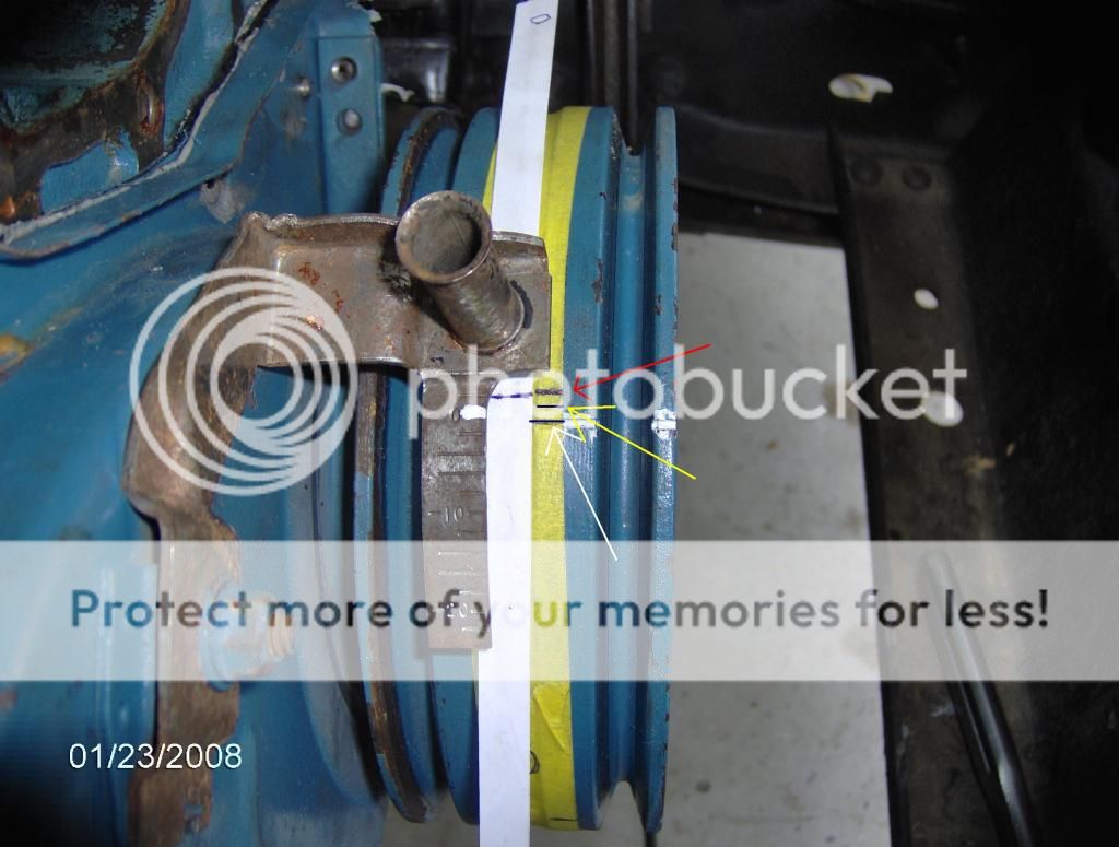
Not too overthink or complicate things but I just checked it again but instead of having the screw ( on the TDC tool ) adjusted down as far as it would go into the cylkinder I instead had it almost all the way up and just barely down into the cylinder.

Now I get a reading of TDC just in between the original line that is on the dampner.

Red line indicates TDC with TDC tool down in the cylinder as far as it will go.

Yellow line indicates TDC tool just a tad into the cylinder

White mark is the original timing line on the dampener.

Can anyone explain this? User error. I do not think so, I was and am very careful with things.

 
I think you should get a degree wheel. Make your own pointer and find out where TDC really is on that balancer in relation to the engine. To "ME" it does not look like the blue balancer has slipped. The elastomer ring looks great. Now the black one looks like ***. I wouldn't trust it at all. Might be all you need to do is tweak the factory pointer a little bit.
 
to use the stop method you need a degree wheel. With the stop you rotate the motor until you hit the stop and read the * on the wheel. then rotate till you hit again and read. Then add the 2 together and /2. this will give you the number.

If you just install the stop and go up again it your just stopping the motor from TDC earlier or later = different timing
 
You don't "need" a degree wheel.

Here's how you use a piston stop:

Adjust or make the stop long enough that it stops the piston "down a ways" from TDC. You want a "fair amount down." imagine in your mind the crank. As the crank comes up towards TDC, the piston SLOWS DOWN, that is, the piston moves VERY little as the crank comes "up and through and over" TDC

I would want, say, "at least an inch" on each side of TDC. You regulate this with piston stop depth. You MUST figure a way to lock (nut) the plunger -- many commercial ones do not-- to keep the plunger from moving. This is IMPORTANT

Bring the piston up by rotating the engine until the no1 piston stops on the device. Make a temporary mark on the balancer carefully, accurately, under the TDC pointer on the timing "tab".

Rotate the engine backwards until the piston again stops. Make a second mark on the balancer.

"True" TDC is halfway between those two temporary marks

The further away (rotationally, or "down in the bore" from TDC that you stop the piston, the more accurate this will be, because when the piston is further down in the bore, a small change in crank rotation results in a LARGE change in piston position. When the crank throw is at 90* to the cylinder bore (about halfway through the stroke) that is when the greatest change in the piston as relates to crank rotation "happens."

If you desire to degree the balancer, you STILL DO NOT need a degree wheel. You can easily measure circumference (around) the damper, and calculate how many degrees per inch you have there. Then, just measure off that distance.

I usually measure off for 40 degrees (V8s). You MUST use a flexible tape (not dividers!!!) for this part of the job.

Once you have TDC and 40 degrees, then you can switch to dividers. Divide the 40 to 20---which you can check from both directions, IE from the TDC mark to 20, and from 40 "back to" 20.

Then you can divide in half again for 10 degree marks, etc.

This requires patience and "no beer." It's easy. Done it many many times. The "old blue" piston stop I made for SB V8s was made sometime in the 1970s

http://www.forabodiesonly.com/mopar/attachment.php?attachmentid=1714540100&stc=1&d=1347066506
 
OK. Well, too many cooks in the kitchen now. I will back out to avoid further confusion. If you want my input, I will be happy to offer it through a pm. There are just too opinions about how to go about it now. None of them are wrong, but you need to nail one down and do it.
 
This is the way I did it, [ame="https://www.youtube.com/watch?v=xg6eAWWvrPA"]finding top dead center . - YouTube[/ame] this sounds like the way that 67dart273 explains it and explained it in an earlier post, that is what I have been going off all day.

Anyway I went back, re-did the deal with the piston stop all the way down in the bore and again I came up with a slightly different TDC.........at this point I am going to assume I was wrong with saying in previous post it was not user error.

I believe that there is a bit of room for error cause I am using ball point pens.....eying it from a 2 foot distance ( one change of the neck make the line jump just a little if you get my meaning ).........and a folded piece of paper ( not the most scientific method!! )

At this point I am as sure as I can be that the dampener has shifted, not much but enough to where I am going to get it repaired per nm9s suggestion. Ill call damperdudes on Mon and get it sent out. Hopefully they can powdercoat it while apart.

Thanks each and everyone of you guys for your efforts, you all have helped me to understand things better I.E theres more than one way to skin a cat!
 
OK. Well, too many cooks in the kitchen now. I will back out to avoid further confusion. If you want my input, I will be happy to offer it through a pm. There are just too opinions about how to go about it now. None of them are wrong, but you need to nail one down and do it.
Please do not back out, everyones input is helpful.

Now that I know where I stand with this dampener thing I do know that the shizzy #2 truck ( parts truck ) has a dampener on it that pretty damn close for what I want to do with it.

Id like to know learn how to check valve timing, I have no specs for the cam that is in truck #2 but I am assuming it is stock.

I have no specs for cam that is in truck #1 but again assuming same.

I would like to learn how to check and see if timing chain/valve timing is operating correctly, I would like to understand how to see if maybe one of the cams is advanced or retarded a bit.

Should I continue this thread or start a new one?
 
Well I said that because there are just too many opinions on how to do it. While I agree 100% with Del, you really don't need a degree wheel, at this point, "I" think you'd be better off using one. There are just too many inconsistencies thus far and a degree wheel would help eliminate them, IMO. But as I said, none of the methods mentioned is wrong. Having said that, you are using one of the methods described and coming up with several different results. That's why I recommended the degree wheel. That's sometimes a problem on forums. Everybody has a different approach and sometimes none of them are wrong. When they are all thrown at you at once, it can get confusing. That's why I said just pick one and go.

Oh and lastly, I would want the lightest balancer available, not the big heavy industrial unit. ALL slants are internally balanced, so there's no difference there. The lighter the reciprocating mass, the less stress is involved. It will even rev a little quicker with a lighter balancer. All of this of coarse is my opinion. Use what you like. As long as the balancer has not slipped, it will be fine I am sure.
 
You can do this either way. You can even find degree wheel photos on the www, and print them out, and glue them to a disc and make one

The thing is...........I doubt you can buy a degree wheel locally

The MAIN thing is to be careful, use patience, and double check your results. "Draw it out" if necessary.

If you use the stop, and the stop is "SOLID" that is, does not move, you will have very very little error, within one degree, certainly.

In a V8, the piston pistons are offset from the center line of the piston, so this adds some error when using a piston stop---but certainly not as much as a degree.

Now in your last check, "about how far" from TDC were your two outer (temporary) marks? I would say at least 15--20 degrees would be good. If not, make a longer plunger for your stop device.

Once again, it is important to add a lock nut to the stop and to get it snug in the plug hole, to prevent the stop from moving.
 
I am going to try it the degree wheel way tomm morning. Maybe I will see that it will take some of the guesswork out of the process. Maybe I will get more consistent results.

I already have the wheel.


I have a few questions RRR and have sent a P.M as you suggested. Thanks
 
Today I found TDC with the degree wheel, I practiced a few times per engine and I can see that doing it this way leaves very little room for error. Every time I tore it down and then re-set it up I got the same end readings versus the few degrees variations every time I tried it with just tape/measuring deal mentioned above.

If anyone would like me to give the procedure here line by line I will do so, just ask. There is alot of info avail on-line but in my opinion alot of it is confusing and most of it dosent seem to quite jive with each other.

There is alot more to it than I had expected.

Long story short the balancer on my 86 restored truck has slipped 3 degrees, ( doing it this way I can say 3 and not 2-3 ish ) the balancer on my parts truck has slipped one degree.

Can someone tell me how much one degree is going to affect my measurements when it finally comes time to degree the cam? I dont know how many thousands of an inch 1 degree =.

The 86 flywheel will be sent to damperdudes, they will re-build it for 107 plus whatever they charge for the powedercoating.

The parts truck balancer I may leave alone if I can get the cam degreed with it still or I may try another spare I have to see if it has spun.


I can load some pictures as well if there is any interest.
 
-
Back
Top