Diagram , Photos connecting dashboard
- Thread starter mecanovi
- Start date
-
cudajim
cudajim
You're going to have to be a bit more specific. What year/model of car are you working on? What does "the sensor engine" mean? Also, what are you asking when you say "a fuel gauge for the dashboard". Do you want to use an aftermarket gauge or get the existing one working or what?
hi,
Can you give me a diagram or photos of connecting the sensor engine and a fuel gauge for the dashboard ?
thank
67Dart273
Well-Known Member
Someone just posted a link to the rear of the dash on one of these not long ago.
I can't help with photos, but here's what may be helpful diagrams
http://www.mymopar.com/downloads/1964/64ValiantA.jpg
http://www.mymopar.com/downloads/1964/64ValiantB.jpg
I don't know how close the 64 is to the 66 cars, but here's a 66 shop manual you can download for free:
EDIT it appears that the 64 and 66 are NOT the same
http://www.mymopar.com/downloads/servicemanuals/1966_Plymouth_Service_Manual.zip
In the shot below, which is from diagram "A" above,
A, orange, is the dimmer controlled dash lamps feed, IE gauge illumination
B, LT GREEN, is left side turn signal indicator
C, TAN, is right side turn signal indicator
E, VIOLET, is from temp sender
F, LT BLUE, is from fuel sender
G, BLACK, is switched accessory power from ignition switch
H, GRAY, is from oil pressure switch
J, DK BLUE, is switched "ignition run" from ignition switch
Attachments
BillGrissom
Well-Known Member
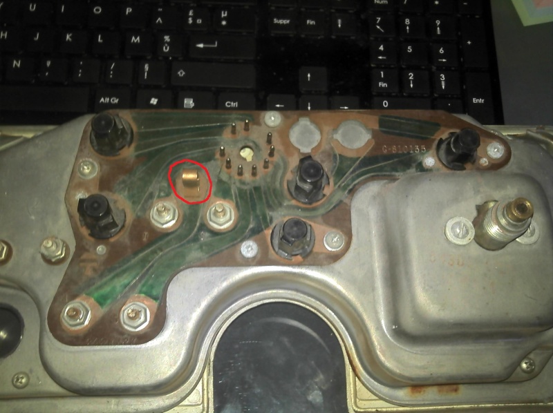
Your dash voltage regulator (Vreg) is inside the fuel level gage. The pin you circled in red is the Vreg output, as I recall. These circuit boards are so simple that anybody can trace the paths to each element. There are no traces on the other side.
I had the cluster in my 65 Dart out a year ago, and currently have my 64 Valiant cluster out, awaiting work. Some maintenance & upgrades you should consider:
1. replace the internal Vreg with a new electronic one. Search "voltage limiter" and "Plymouth" on ebay ($25). There was a post here a week or so ago with links to photos (RT Engineering or such, I recall).
2. Check and resolder the circular connector pins. The solder joints often crack.
3. Sand the ammeter connections and tighten well. Use silicone dielectric grease. These terminals carry up to 40 A, so can overheat and melt if corroded. If you upgrade your alternator, look up my post on adding bypass diodes in the engine bay to protect the ammeter but leave operational, or just bypass it totally in the engine bay.
4. Replace the lamps bulbs with LED type (ebay). Cheap, should last forever, and look nice. Also, sand the copper and grease.
5. Check the speedometer. It should not wobble in the bore, and the needle should move smoothly when you spin it with a drill. If loose, the spinning magnet will eventually grab the aluminum cup and break it (bad) or your cable (better). I had the one in my 65 Newport re-bushed at a speedometer shop long ago.
6. For looks, remove the clear lenses from the chrome plastic and polish. Not easy since you must drill the plastic posts and epoxy back. I also removed the bad chrome paint w/ a soak in Super Clean. I had all dash plastic "rechromed" at Sacramento Chrome for $110.
Good Luck
Hi ,
I buy a voltage limiter "VRC601" http://www.ebay.com/ctg/Standard-Mo...nt-Cluster-Voltage-Regulator-Switch-/74411208
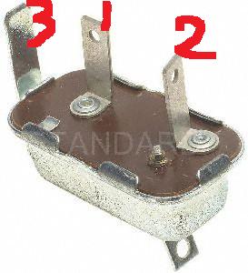
je l'ai branché en :
1 : 12v
3 : ground
normalement en 2 je devrais avoir 5 v et bien non j'ai 12v
What ?????
I buy a voltage limiter "VRC601" http://www.ebay.com/ctg/Standard-Mo...nt-Cluster-Voltage-Regulator-Switch-/74411208
je l'ai branché en :
1 : 12v
3 : ground
normalement en 2 je devrais avoir 5 v et bien non j'ai 12v
What ?????
Rocky_JS
'cuda
Here mecanovi, this should show how the wiring runs on a basic conversion. As mentioned you do need to disable the voltage regulator in the fuel gauge.
http://www.slantsix.org/articles/instrument-reg/instrument_reg.htm
http://www.slantsix.org/articles/instrument-reg/instrument_reg.htm
norshorblufish
By the Big Water
If it's an internal one it should be like this.
This is for a later model car . It's the same as previous posted except for disabling the one in the fuel gauge.
http://rt-eng.com/rte/index.php/RTE_Gauge_Faq#Fixing_dash_clusters_that_have_internal_limiters
This is for a later model car . It's the same as previous posted except for disabling the one in the fuel gauge.
http://rt-eng.com/rte/index.php/RTE_Gauge_Faq#Fixing_dash_clusters_that_have_internal_limiters
Rocky_JS
'cuda
If it's an internal one it should be like this.
This is for a later model car . It's the same as previous posted except for disabling the one in the fuel gauge.
http://rt-eng.com/rte/index.php/RTE_Gauge_Faq#Fixing_dash_clusters_that_have_internal_limiters
nice find, I was looking for that diagram. lol
norshorblufish
By the Big Water
I knew I had it bookmarked some where.
Rocky_JS
'cuda
If you do not already have one. My recommendation is this. there is also a wiring diagram on how the wiring should be connected.
http://www.demonivr.com/Superior.html
http://www.demonivr.com/Superior.html
norshorblufish
By the Big Water
I don't know about anyone else but all I get is the French language on this end.
That's probably why you aren't getting any response back.
I'm one who never studied a different language.
That's probably why you aren't getting any response back.
I'm one who never studied a different language.
Finalement je vais faire ça :
http://www.allpar.com/history/mopar/electrical2.html
http://www.chargersourceguide.com/voltagelimiter.html
et j'ai acheté ça , je me prendrais moins la tete:
http://cgi.ebay.fr/ws/eBayISAPI.dll?ViewItem&item=270824968672&ssPageName=ADME:L:OC:FR:3160
http://cgi.ebay.fr/ws/eBayISAPI.dll?ViewItem&item=150827161295&ssPageName=ADME:L:OC:FR:3160
Rocky_JS
'cuda
oui ils travailleront
'ai reçu ce matin le régulateur electronique , le condensateur et j'ai le montage
ensuite j'ai remonté le tableau de bord apres avoir testé les jauges d'essence et de temperature .
Entrée jauge essence 5v , sortie 5v , jauge OK
Entrée jauge t° 5v , sortie 0v , jauge HS
La jauge d'essence ne fonctionne pas .
J'ai mis le fil sortant de la jauge d'essence à la masse et la jauge monte
continuité du fil jusqu'au reservoir ok
La jauge dans le resservoir doit etre HS (5.02 Mohm)
la jauge est facile a remplacer car elle est sur le devant du reservoir
Rocky_JS
'cuda
at the senders temp, oil pressure use a 10 ohm resistor attach one to the wire and ground the other end with key on gauge should read full/Hot/High.
J'ai 4.25 M ohm
est-ce que ça peut etre un probleme de masse sur le reservoir car il a été repeint ?
http://www.ebay.com/itm/Mopar-Fuel-...Parts_Accessories&hash=item43b31cd037&vxp=mtr
est-ce que ça peut etre un probleme de masse sur le reservoir car il a été repeint ?
http://www.ebay.com/itm/Mopar-Fuel-...Parts_Accessories&hash=item43b31cd037&vxp=mtr
anthonyjelia
Member
RT eng is no longer in business # is disconnected and they don't reply to email.
1968notch
Too many projects, not enough time/$$$
Hi , I buy a voltage limiter "VRC601" http://www.ebay.com/ctg/Standard-Mo...nt-Cluster-Voltage-Regulator-Switch-/74411208
Finally, someone provided a "pin-out" of this style regulator. Even though it's in French, I get it. I bought one of these thinking it fit my 68 barracuda but i don't think it does. I have the gas guage regulated type I think. But since I have one of these now, i was going to use it instead of the solid state types since it is better designed to work the guages properly (although not as trouble free as a solid state type).
What I don't get is why the guy at napa sold it to me in the first place since I told him what type of car it was for, plus it was a special order. I'm glad he did though, although I did pay quite a bit more for it than the ones on e-bay, but they aren't echlin's either.
I will be using the 3 wire connection pic linked to earlier in the thread. I actually think my circuit board is cracked as well which my be part of my problems. Don't know for sure but given all the crap that's wrong back there, it has to be something that cuts across multiple circuits, like a crack or a main voltage feed. Only a couple of the lights actually work (after a replacement of all I could reach). Thanks again for this thread, all the responses and all the links provided.
Paul
BillGrissom
Well-Known Member
1968 notch,
Most 1968 cars would have the "plug-in" Vreg in the photo (my 1969 Dart did). However, if your car has a tachometer ("rally dash"), then your Vreg is still inside the fuel gage (until ~1973). I doubt you could easily adapt the 3 spade box you have. I would take it back to NAPA, or if you lucked out and paid <$15, perhaps flip it on ebay since I recall they often sell for $50. The electronic Vreg works much better, unless you think a slightly pulsing needle is preferable (artifact of old thermal on-off control). Buy a "voltage limiter" with ring terminals ($30 ebay). You must open your fuel gage and disable the internal Vreg. I slid heat shrink over the wire-wound arm.
With an electric Vreg, you can adjust the voltage to get your fuel gage to read correctly at "E", or "F", or your temperature gage to read correct. Pick 1 of 3. My preference is knowing exactly where "E" is. There are other mechanical tweaks on the gage, but a bit tricky. I added resistors to fine tune all 3 readings.
-


