Elec ignition upgrade question

-

ValiantOne

Well-Known Member
Joined
Mar 20, 2008
Messages
1,117
Reaction score
210
Location
West "By God" Virginia
Hey All,

I have a 68 Valiant which has already had the charging system upgrade from electromechanical to electronic done like picture #1 below.

I got all my parts to do the elec ignition upgrade and dug up the wiring diagram like picture #2 below.

The question is, am I installing a second ballast resistor for the ignition upgrade? Or do the charging system and ignition share a ballast resistor? If they share, does anyone have a complete schematic for a 2 prong ballast?

Thanks,

CE
 

Attachments

  • charging system old and new style.jpg
    21.2 KB · Views: 225
  • elec ignition.jpg
    28.5 KB · Views: 235
You should only need one ballast reistor. I am running a Mallory ignition now but I did do the electronic ignition upgrade years ago.
 
If there is only one ballast resistor (that is what I was hoping!) then the question becomes simple.

of the wires coming off the ballast resisitor, the +coil, and two ignition wires to the bulkhead should be the same, right?

So do I just splice the blue wire from the ECU into the blue wire that runs from the ballast resistor to the Elec. Voltage Regulator / Alternator?

Thanks,

Chris E.
 
There is a 4 pin and a 5 pin ECU, the two prong goes with one and the 4 prong goes with the other. At least I think I got that correct. My car is a 5 pin with a 4 prong ballast if I remember correctly.

Maybe Del will jump in here and help.

And yes, you only need one ballast. Well, maybe two, (one in the trunk for a spare, lol).
 
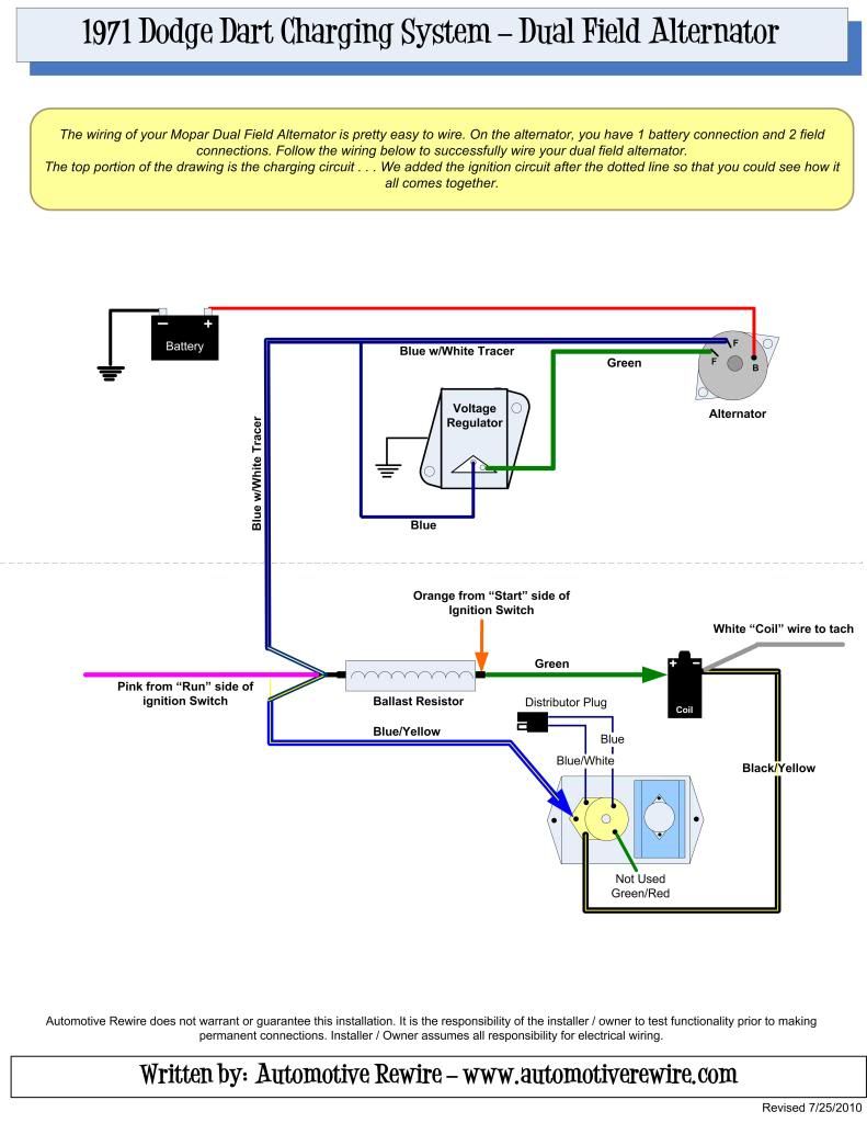
maybe this will simplify it for you.. look at them as two stand alone systems that just happen to tie in together at some points.
.
your wire colors may differ.
71DartChargingWiring.jpg
 
"The deal" on the dual ballast

In the early days of Mopar breakerless ignition, the second section of the ballast (4 terminal ballast) was part of the power supply TO the ignition box. This was later re-designed and the ballast then went back to a 2 terminal ballast

If you compare the diagrams with the 4 pin ECU and 2 pin ballast, you will find that the 2 pin setup for the newer ECU is wired EXACTLY like the old "points" system

IN FACT you can toss you points dist. in the trunk for a spare. If the ECU system ever quits (and it's not a bad ballast or bad coil) all you need to do is slap your old distributor back in, unplug the ECU connector, and hook the old dist. wire back up to the coil.

You can not tell by looking (always) if an ECU is 4 pin (2 terminal ballast) or 5 pin (4 terminal ballast) because some boxes HAVE all 5 pins.

MOST boxes you are going to "run into" nowadays, and probably ALL new boxes are going to be 4 pin box / 2 pin ballast

=============================

ON YOUR VR conversion. I've written about this a lot. VOLTAGE DROP to the VR ign terminal is a big deal, is the probably main cause of over voltage to the battery.

PLEASE take the time to check, ...............easy

Turn the key to run, engine stopped. Hook your meter probe to "as close as you can get" to the VR IGN terminal. This might be your ballast, or the field terminal on the alternator.

Hook the other probe to battery POSITIVE.

You are hoping for a very low reading, the lower the better. Over .3V (3/10 of one volt) means you need to improve things.

The "path" for this and probable drop is......

Battery.......starter relay.........fuse link........through bulkhead (red).........to ammeter.......through ammeter and out black........to welded splice.........to ignition switch connector.......through the switch........out ignition switch connector on the blue "run" (ign 1) and back out through the bulkhead, .......to the ignition, the field, and the regulator

MOST PROBABLE are poor connections in the bulkhead connector, ignition switch connector and switch, and ammeter. Least probable, but has and can happen, is failure of the welded splice.

HOW to fix........Easiest, in some respects, if the charging wire part of the bulkhead is OK, is to add a relay to run the ignition and charging system. Otherwise, fix the poor connections wherever they are. As some ignition switches are getting more difficult to obtain, this might be a trick.

==================================

GROUNDING. Make absolutely sure the VR and the ECU is grounded. Scrape paint off the back of the flanges, and around the firewall bolt holes. Use star lock washers. they MUST be tight.

CHECKING grounding. After you get things wired and running, and confirm it's charging properly, warm it up and get the battery "normalized." Then make this check, first with all accessories off, and again with lights, heater, etc powered on

With engine warm,and running fast idle to simulate "low cruise," stab one meter probe into the battery NEG post. Stab the remaining probe into the VR mounting flange. You are hoping for a very low reading, zero is perfect. More than .2--.3V means you need to improve grounding.
 
Very interesting info. Going to break out the meter and do some probing when the conversion is complete.

Thank you,

CE

"The deal" on the dual ballast

In the early days of Mopar breakerless ignition, the second section of the ballast (4 terminal ballast) was part of the power supply TO the ignition box. This was later re-designed and the ballast then went back to a 2 terminal ballast

If you compare the diagrams with the 4 pin ECU and 2 pin ballast, you will find that the 2 pin setup for the newer ECU is wired EXACTLY like the old "points" system

IN FACT you can toss you points dist. in the trunk for a spare. If the ECU system ever quits (and it's not a bad ballast or bad coil) all you need to do is slap your old distributor back in, unplug the ECU connector, and hook the old dist. wire back up to the coil.

You can not tell by looking (always) if an ECU is 4 pin (2 terminal ballast) or 5 pin (4 terminal ballast) because some boxes HAVE all 5 pins.

MOST boxes you are going to "run into" nowadays, and probably ALL new boxes are going to be 4 pin box / 2 pin ballast

=============================

ON YOUR VR conversion. I've written about this a lot. VOLTAGE DROP to the VR ign terminal is a big deal, is the probably main cause of over voltage to the battery.

PLEASE take the time to check, ...............easy

Turn the key to run, engine stopped. Hook your meter probe to "as close as you can get" to the VR IGN terminal. This might be your ballast, or the field terminal on the alternator.

Hook the other probe to battery POSITIVE.

You are hoping for a very low reading, the lower the better. Over .3V (3/10 of one volt) means you need to improve things.

The "path" for this and probable drop is......

Battery.......starter relay.........fuse link........through bulkhead (red).........to ammeter.......through ammeter and out black........to welded splice.........to ignition switch connector.......through the switch........out ignition switch connector on the blue "run" (ign 1) and back out through the bulkhead, .......to the ignition, the field, and the regulator

MOST PROBABLE are poor connections in the bulkhead connector, ignition switch connector and switch, and ammeter. Least probable, but has and can happen, is failure of the welded splice.

HOW to fix........Easiest, in some respects, if the charging wire part of the bulkhead is OK, is to add a relay to run the ignition and charging system. Otherwise, fix the poor connections wherever they are. As some ignition switches are getting more difficult to obtain, this might be a trick.

==================================

GROUNDING. Make absolutely sure the VR and the ECU is grounded. Scrape paint off the back of the flanges, and around the firewall bolt holes. Use star lock washers. they MUST be tight.

CHECKING grounding. After you get things wired and running, and confirm it's charging properly, warm it up and get the battery "normalized." Then make this check, first with all accessories off, and again with lights, heater, etc powered on

With engine warm,and running fast idle to simulate "low cruise," stab one meter probe into the battery NEG post. Stab the remaining probe into the VR mounting flange. You are hoping for a very low reading, zero is perfect. More than .2--.3V means you need to improve grounding.
 
I re-iterate what AbodyJoe said.
The charging system does not have a ballast resistor. Any connections to the ballast are simply because the IGN circuit powers both Vreg and the spark system (via ballast).

On a similar vein, you may someday get confused by some wires going to your wiper switch. Some use terminals on that switch as a wiring convenience and do not involve the wiper.
 
-
Back
Top