Fleet Wiring

-

jarvitron

Well-Known Member
Joined
Jan 10, 2012
Messages
107
Reaction score
10
Location
Portland, OR
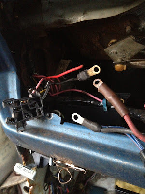
Hello - I'm trying to find some information about "fleet" or "taxi" wiring (from the factory). I was trying to look at my harness to see if I needed to do a bulkhead bypass, and found that I have two ~8 gauge wires passing through their own rubber firewall grommet versus a large wire connected to the bulkhead, and the wiring appears to be protected by fusible links as specified in all the bypass conversion guides. Does my car have "fleet" wiring? Anybody have a car with this from the factory that can share a picture of theirs? I still have an ammeter, if I don't bypass it, will I fry my harness? I'm getting ready to do a magnum swap and want to know if I need to upgrade my wiring or bypass the ammeter/change to a voltmeter for the heavier alternator. I'll snap pictures of the firewall connection when I get home.
 
What makes you think that someone didn't just do some rewiring prior to you owning it?

"Fleet" usually means build it cheaper not build it better. The wire passing through a grommet doesn't sound like anything the factory would have done.
 
Very little else under the hood has been touched, aside from stripping off emissions, and what little electrical has been touched by previous owners looks nothing like the overall quality of the wiring on this portion. I see no obvious home mechanic type wiring connections (butt connectors, spades, or electrical tape - interior electrics which have been touched feature all three along with duct tape and wire nuts) on this section of the harness either. I've been reading about the bulkhead bypass and have seen references to "this is how fleet cars were wired from the factory", and was curious if anybody had any documentation on that or if it's just folklore.
 
sounds to me like someone before you did this bypass. just because it doesnt look like a shade tree job, doesnt mean it wasnt. not to mention you have no pics for reference. i just did the ammeter bypass and with exception of 2 wires, you cant even tell. and i added a volt gauge because a melted ammeter gauge is nothing nice. unless there was some kind of bulletin from chrysler or a recall , i dont think any dealer bypass was ever performed. that would have meant every police car, taxi or service vehicle would have been subject to this.
 
According to the AllPar site:

from here:

http://www.allpar.com/history/mopar/electrical.html

"police, taxi, and fleet vehicles, whose electrical loads were typically quite high (and which vehicles typically had a “fatter” alternator) had the two charging-circuit conductors removed from the bulkhead connector, and its woefully-inadequate 1/4-inch Sta-Kon connectors, and run directly through the firewall (with a simple rubber grommet). If you’ve experienced firewall connector problems, you should consider this mod as an option."

So it sounds like it could be true

I've forgotten, the C barges went to external shunt ammeters as early as 71?2? in some of the big cars

(The '72 shop manual shows 72 Fury and Chrysler was external shunt but the Imperial was NOT!! You can tell by the gauge of the wires. The Fury and Chrysler show no18 wires to the ammeter, indicating an external shunt device)

But even the Satellites show a separate grommet on the optional 65A alternator right in the wiring diagram.

This bulkhead mess is nothing new. Seems to me my old '70 sixpack RR was supposed to have a 65 A alternator and came instead with a 60? A because it was wired through the bulkhead like any other car. The original owner (K7WWA) and I were both amateur radio ops, and INTENDED to install equipment in the car. During the time I had it, the bulkhead connector failed miserably, melted the housing. I ran new wires for the heavy current stuff "straight through" and this was LONG before Al Gore invented the internet.
 
well, if thats the case, then i guess i learned something new today. you would think that if they were going to pick and chose certain vehicles to do this to, and they knew there were possible issues, they would have just done this all across the board...
 
Here are a few pics of the wiring.

Here's what the connectors used throughout looks like disconnected.
photo-27.jpg


Here's where it passes through the firewall.
photo-25.jpg


And here's the fusible link connection to the (starter relay?) module just rear of the battery tray. All wiring diagrams I've seen that indicate a fusible link at this location is "for 65A alternator or taxi".

photo-26.jpg
 
Your photos didn't load. I am assuming this is the 73 Dart in your signature. My 64 Valiant has ammeter wires run thru grommets in the firewall and that might be factory since I don't see any positions in the 2 bulkhead connectors that would have been used. Also it sure wasn't a taxi or cop car since a convertible. My two 65 cars (A & C) have a dedicated feed-thru lug as part of the bulkhead (screw attachment, not standard 57 spade terminal).

To answer your main question, whether a factory "fleet" or later upgrade, it will work fine in not melting wires or connectors. One question is whether your existing ammeter can handle the increased current of a Magnum alternator (if you keep serpentine belt setup). At a minimum, clean the terminals on the cluster and use silicone grease. I suspect your factory ammeter pegs higher than 30 A since I have never seen one go near full scale.

If really concerned, look up my post on using diodes to shunt any excess current. Even easier is to just wire around the ammeter in the engine bay and use a voltmeter. Since Detroit started skimping on electrical monitors, I use the "voltmeter in cigarette lighter" solutions in my newer cars ("Equis" or such, $15 on Amazon). It is much better than the "car dies with no warning and dash goes crazy" factory solution that bit me a few times.
 
Hrm, see if they load now. If not I'll upload them somewhere else. Yeah, I'm planning on keeping the serpentine accessories. I have a voltmeter (sunpro recommended in another bypass /voltmeter swap thread) ready to go for this. Presumably all I need to do is connect both sides of the ammeter wiring together, then tap into that for the voltmeter.
 
Hrm, see if they load now. If not I'll upload them somewhere else. Yeah, I'm planning on keeping the serpentine accessories. I have a voltmeter (sunpro recommended in another bypass /voltmeter swap thread) ready to go for this. Presumably all I need to do is connect both sides of the ammeter wiring together, then tap into that for the voltmeter.

A volt meter needs to be on a switch circuit. The amp gauge wires are hot at all times. The volt meter there would drain the battery.
 
You need to tap into the dark blue "run" wire feeding the instrument cluster for the voltmeter.

I would say from your photos that there is no doubt that is either factory wiring, or a dealer installed "fleet" kit of some sort. I don't know where to find documentation of it, though.
 
So, to answer myself, I guess - I finally decoded the fender tag and found both J16, heavy duty wiring, and F18, which appears to code for 65A alternator. Interesting car. Also see heavy duty cooling N51 (max engine cool), which I assume means "it has the fan shroud".
 
Resurrecting this thread (and the car) from the dead. I pulled the dash to troubleshoot the no gauge/no light issues and replace all bulbs/clean and dielectric the connectors. I realized that the ammeter was looking crusty (corroded heavily) and since the fancy factory wires were boy/girl, bypassing the ammeter is as easy as connecting the wires straight through, which makes it alternator stud -> Starter relay through fusible link. I removed the crusty looking dead gauge and blocked off the instrument panel spot for the ammeter, HOWEVER -- There are two mystery wires I need to figure out before I put the dash back together.

2012-08-18.jpg


The two wires coming from the right are the (now bypassed) bulkhead wire from the alt to ammeter and return to the starter relay.
The pink wire with the tape is a hookup for a stereo which heads under the bench seat to the passenger side for an amp.
The red wire with no end and the black wire both come out of the same harness as the headlight switch connector. I _think_ the red wire goes back to the main bulkhead connector on the firewall, it has conductivity to the main "positive" bulkhead pin, but I have no idea where the black wire goes. The red wire wasn't hooked up before and the car was running fine.

Anybody know what circuit comes into the dash in the same bundle as the headlight switch connector? Otherwise I guess I'm bustin' out the conductivity meter and getting my upside-down-electrician on tomorrow, not fun.
 
Max cooling package would have given it a 26 inch radiator not just a shroud. You would get a shroud if you got ac or max cooling package.
 
Jarv I looked this up in the '74 manual. That is EXACTLY how "fleet wiring" was done. The red was the original "standard" battery infeed, and it's capped off with the addition of the grommet / heavy wiring feed through. The black is the original black ammeter wire, and it gets connected to the heavier black ammeter wire of the fleet wiring.

The original black goes into the in -dash harness, and there's a big factory splice in there. That splice feeds

headlight switch (headlights only) power

the "hot" fuse panel buss

the ignition switch

Maybe one or two other things, it seems to feed the seat belt interlock module as well
 
Yeah, if I did get HD cooling like the fender tag says (and it does) I'd have a 26 inch radiator with a shroud (and I do have that, never stated anywhere that I didn't). So there's two mysteries solved -- fender tags are usually right and these dash wires are NOT connected to the radiator (I just double checked for ya). ;)

Hrm. Maybe for simplicity's sake I should un-bypass those wires and just hook all three - the red/black from the fleet wiring and the black from the harness, together with some dielectric and a little heat shrink over the whole mess - it's all pretty heavy duty wiring and the bulkhead connection is very nicely done, I don't want to unintentionally overload the bulkhead connector by taking out a second path for all the interior wiring to draw current. Any drawbacks other than six additional feet of wire between the alt and solenoid that I'm missing?
 
-
Back
Top