rmchrgr
Skate And Destroy
Thought I'd share what I had accomplished over the last few weeks or so with the fuel delivery system on my Duster.
Initially, fuel delivery was/is handled by a stock tank, 3/8" line, Carter 6270 street/strip mechanical fuel pump, steel line to a generic, chrome dual feed line which ultimately supplies a Proform 750 double pumper. There was also a cowl mount Auto Meter Phantom fuel pressure gauge tee'd off of the dual feed line with a braided hose.
I got the car in March. Since that cowl gauge was right in my face, it only took a little while to realize that the fuel pressure was really high, like 11-12 psi. To my knowledge, this is almost double what it should be for a simple carbureted fuel system.
At first, I thought that the cowl gauge might not be right so I went about verifying what the actual pressure was at the gauge fitting. I brought a fancy fuel system tester home from work and snapped it in. Sure enough, that Carter was pushing out 11-12 psi.
So the pressure was really high and the float level was almost to the top of the sight glass. Not sure if this was the result of the pressure or what but generally speaking both pressure and float level needed to be lower. Interestingly enough, the car seemed to run OK but I didn't really have anything to compare it to. Also, one of things on my future upgrade list is an analog air/fuel gauge to aid in tuning. If it is to be remotely accurate, I needed to get the fuel pressure in line.
Obviously, the first step in reducing fuel pressure was to install a regulator. Once you arrive at this point, you have to figure out how to mount and plumb the thing into the delivery system. There's a lot of options out there and the one I decided on necessitated changing everything between the pump and carb.
Most of the literature you read says that its best to have the regulator close to the carb. which sounds sensible to me. There are several styles of regulator brackets that mount to the passenger side carb studs. I chose one from AED which only mounted to the front stud. AED also had a set of stainless inlet lines I picked up that can be used with the bracket. The lines come pre bent and flared for AN fittings.
Buying the inlet line kit made it necessary to go with AN fittings and hoses since the stainless lines were already AN style. I was happy to change out the hardware store brass fittings that connected everything.
The final piece of the puzzle was which style hose to use. AN stuff usually takes some sort of braided hose but I was never a fan of steel braided hose. I was at Carlise a few years ago and noticed the Muscle Motors giveaway 408 had this cool, black braided hose going from the pump to the carb. I had never seen that type of hose before but i really dug the looks of it. The image stuck with me and I went looking for it when I was ready to buy.
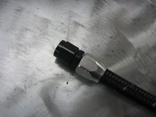
The hose I ended up with was Russell Pro Classic. It's black braided with a a rubber inner hose. This stuff is super light and very easy to work with unlike steel braided. No Koul Tool needed or bloody fingers from smushing the hose into the fittings. I used their Pro classic black and clear anodized fittings and hose ends. Pro Classic is primo stuff and not cheap.
During the planning stage, I learned a lot about fittings and threads. I feel like I have a decent grasp on this stuff now whereas before, I literally had no idea about anything remotely related to hoses and fittings. There is a lot to know about pipe thread, AN thread, 37 degree flares, fittings adapters and so on. I even got a book about which was a big help.
It was very helpful to draw out the system on paper and make notations on all the connections. Flip through a Summit or Jegs catalog, there is a literally a sea of fittings and adapters to wade through. I stuck with Russell to help narrow it down. They make just about anything you could possibly need so it was easy enough to find what I wanted.
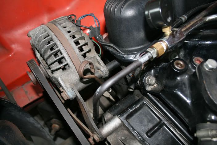
One of the tougher parts was figuring out the angles and/or 'clocking' of the fittings, especially at the fuel pump. The angle of the outlet fitting is 60 degrees from the center line of the fuel pump. The best solution I could come up with for routing the hose up from the pump was a 90 degree adapter from the pump outlet attached to a hose end. The hose end is a little long and kind of ends up right against the lower alternator bracket. It cleared OK but a 120 degree fitting would have been best. Those specialty fittings however are ridiculously expensive, like $30 each. Maybe some other time. To keep the hose from rubbing against the edge of the bracket, I drilled and tapped a hole in it for a rubber hose line clip. Works great.
So it took some doing but it all came together and the new system is working great. Fuel pressure is right at 6 psi. I can't say there is a marked improvement in drivability but throttle response is a tad crisper. I was able to adjust the float to the proper level which is right at the bottom of the sight glass. Whatever the outcome, at least now there is a proper baseline for further tuning.
I definitely had to battle some fuel leaks before it was all wrapped up. The bowl fittings that came with the AED lines came with new gaskets. They looked the same as the ones that were on there already but I used the new ones. They leaked badly, like fuel dripping all over the place. I put the old ones back in and the leaks stopped. I'll also mention that the bowl gasket was completely split and was useless so I got a new one,
In thinking about pressure and float level, I researched a lot about what could cause this situation and I read over and over again that fuel could be pushing past the needle and seat or debris may be caught in the needle and seat itself. I took the needle and seat out and found that the o ring was hard and had a small crack in it. There was no debris lodged in it but the crack in the ring made me think that this may have been contributing to the high float level. Off came the bowl. I cleaned it up and installed a new needle and seat.
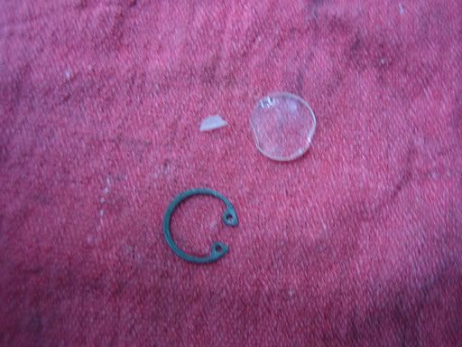
Thought I would also mention that during the initial set up, I broke a fuel bowl sight glass trying to set the float level. I had never dealt with a clear one before, just the screw in type. The glass sight on the Proform is held in by a snap ring and gets sealed with an o ring. I tried removing the sight while the bowl was still on the carb which can not be done. Really, its not necessary to remove it all since you can actually see where the float level is without moving the plug. Doh!
But I digress. So before I had this brilliant epiphany, there I am pinching that snap ring. I got the ring out but when I tried to get the sight out, it became cocked and got chipped. I had to call Quick Fuel (who makes the Proform bowl) to get a replacement. I got 2 for a total of $4.86. I managed to get the chipped on back in and it's not leaking at the moment. I couldn't wait to test out the new stuff and go for a ride. No way was I going to let a stupid chipped sight glass ruin it, even if it was a leaker.
Here are some pics to illustrate what I've been yammering about.
This is what I started with. You are looking at a 12psi fuel delivery system. Note air compressor pressure gauge in gauge port to fill hole where cowl gauge line was.
This is what I was imagining. Note generic parts store chrome dual feed line.
Steel line from pump to carb. More plumber's fittings and the dreaded teflon tape. Yes, I need a new dipstick, Jimmy.
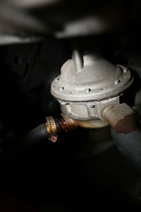
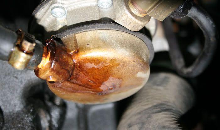
Original fuel pump inlet and outlet. Its a leaker, Vern.
Underside.
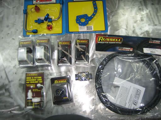
Here is most of the stuff I ordered from Summit: line kit, hose, fittings, gauge, bracket etc. I had the regulator already from a Holley blue electric pump, came as a kit. Regulator is 12-803.
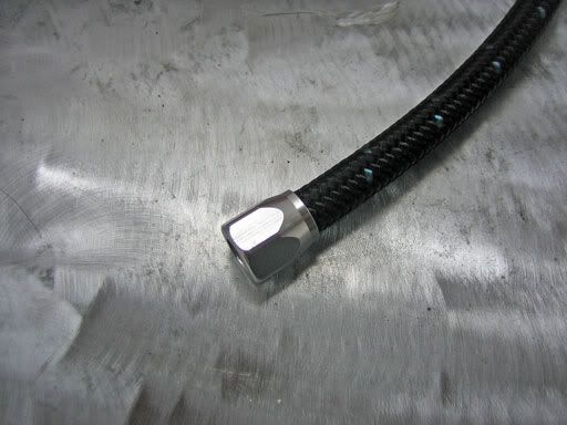
First step was to measure how long of a hose I needed and cut it to length. I took out the steel line and laid the hose on it. I added a few inches before I cut, just in case. Here is the hose cut with an end installed.
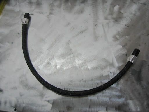
A pic of the completed hose.
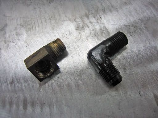
Next was getting the line out of the pump. Here is a comparison shot of the two different outlet fittings. The black one is worlds away from the plumbing supply store fitting. We're not plumbing a sink here gang.
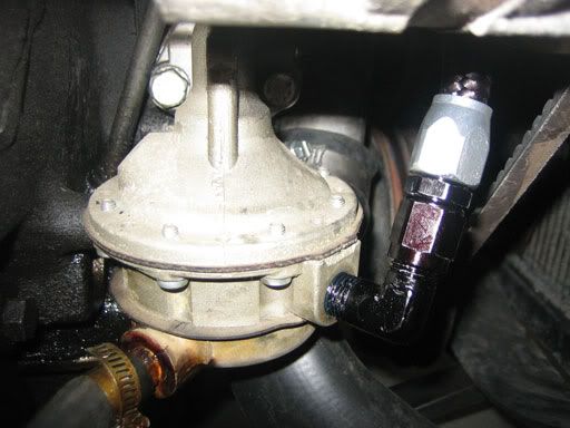
So I have a length of hose with a hose end and a fitting, let's stick it in the pump and see what we have. I used Russel teflon gel sealant for the pipe thread fittings. Works very well. Bye bye plumber's tape. here you might see how how clocking and angles come in to play.
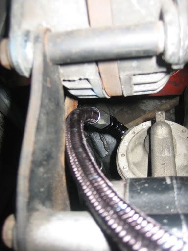
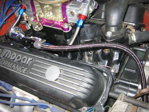
Looking down to the fuel pump from above. Note how the hose end is right against the alternator bracket. that's where i used a rubber clip.
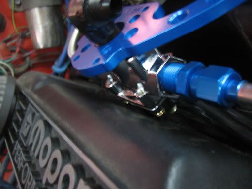
Hose is done and routed, on to the topside. Here's the regulator installed on the bracket. I tried mounting it right side up but the hose end was hitting the intake runner. The bottom of the regulator was also hitting the valve cover and crunching the alternator wires. It's OK to mount it upside down. There is plenty of clearance for the linkage with this bracket, i think it could have been made a little shorter to help clear the valve cover. Or maybe someone needs to come up with a Mopar-specific 59 degree head design.
Pic showing interference points. There was no way this was going to work, the lines would not match up and the angle of the thing was all wrong for this particular combination (small block, Victor 340). Perhaps it might work with different parts.
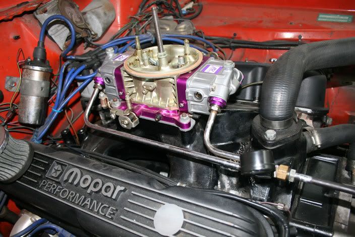
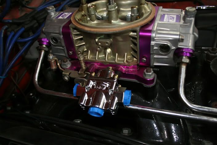
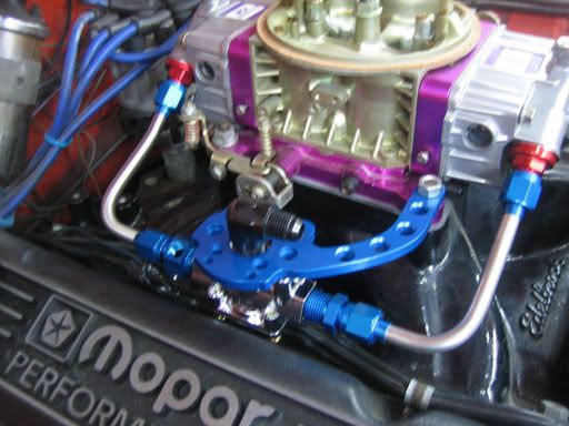
I called AED at this point. I asked if it was OK not to use the bracket and they told me it would be fine, only really high vibration situations require a bracket. Indeed, the steel lines are enough, it's totally solid. I might try to make my own at some point but I can roll with it like this for now. Here is the system without the bracket. I angled the regulator to match the angle of the valve cover.
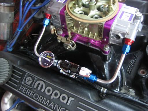
Here it is with hose installed.
Couple other pics. First is the broken sight. Not sure how this isn't leaking but it's not.
Trying to show the crack in the N & S o ring. Hard to see but it's there.
Blown out bowl gasket. How the f*ck does that happen? Probably from sitting for long periods of time with old fuel. Wasn't me for once though...
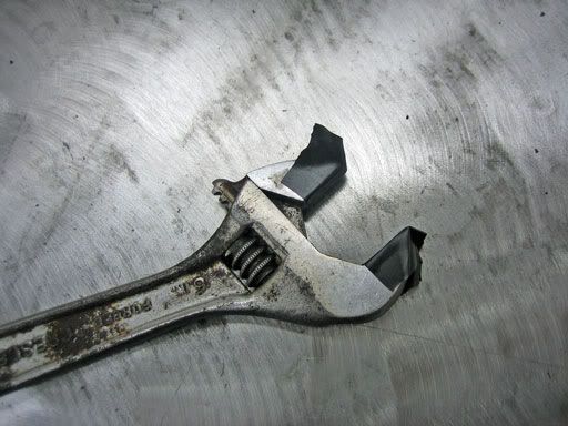
Home made AN wrench. Now that I've done it, I would say it does pay to have one of those specialty AN wrenches, the anodized fittings get galled up pretty easily. I used this until I realized line wrenches work really well.
One more pic of the primo Russell hose and fittings.
Well hey, thanks for reading. Hope you found the writeup enjoyable and or helpful. I had a good time doing this, it was a nice project that didn't break the bank or have the car down for a long time. If you have all the parts, you could do this fairly quickly. The most time consuming part of this project was educating myself on all of this stuff and planning it out. I actually fixed a problem for once and stuck with it through some hiccups to arrive at a decent outcome.
- Greg
Initially, fuel delivery was/is handled by a stock tank, 3/8" line, Carter 6270 street/strip mechanical fuel pump, steel line to a generic, chrome dual feed line which ultimately supplies a Proform 750 double pumper. There was also a cowl mount Auto Meter Phantom fuel pressure gauge tee'd off of the dual feed line with a braided hose.
I got the car in March. Since that cowl gauge was right in my face, it only took a little while to realize that the fuel pressure was really high, like 11-12 psi. To my knowledge, this is almost double what it should be for a simple carbureted fuel system.
At first, I thought that the cowl gauge might not be right so I went about verifying what the actual pressure was at the gauge fitting. I brought a fancy fuel system tester home from work and snapped it in. Sure enough, that Carter was pushing out 11-12 psi.
So the pressure was really high and the float level was almost to the top of the sight glass. Not sure if this was the result of the pressure or what but generally speaking both pressure and float level needed to be lower. Interestingly enough, the car seemed to run OK but I didn't really have anything to compare it to. Also, one of things on my future upgrade list is an analog air/fuel gauge to aid in tuning. If it is to be remotely accurate, I needed to get the fuel pressure in line.
Obviously, the first step in reducing fuel pressure was to install a regulator. Once you arrive at this point, you have to figure out how to mount and plumb the thing into the delivery system. There's a lot of options out there and the one I decided on necessitated changing everything between the pump and carb.
Most of the literature you read says that its best to have the regulator close to the carb. which sounds sensible to me. There are several styles of regulator brackets that mount to the passenger side carb studs. I chose one from AED which only mounted to the front stud. AED also had a set of stainless inlet lines I picked up that can be used with the bracket. The lines come pre bent and flared for AN fittings.
Buying the inlet line kit made it necessary to go with AN fittings and hoses since the stainless lines were already AN style. I was happy to change out the hardware store brass fittings that connected everything.
The final piece of the puzzle was which style hose to use. AN stuff usually takes some sort of braided hose but I was never a fan of steel braided hose. I was at Carlise a few years ago and noticed the Muscle Motors giveaway 408 had this cool, black braided hose going from the pump to the carb. I had never seen that type of hose before but i really dug the looks of it. The image stuck with me and I went looking for it when I was ready to buy.
The hose I ended up with was Russell Pro Classic. It's black braided with a a rubber inner hose. This stuff is super light and very easy to work with unlike steel braided. No Koul Tool needed or bloody fingers from smushing the hose into the fittings. I used their Pro classic black and clear anodized fittings and hose ends. Pro Classic is primo stuff and not cheap.
During the planning stage, I learned a lot about fittings and threads. I feel like I have a decent grasp on this stuff now whereas before, I literally had no idea about anything remotely related to hoses and fittings. There is a lot to know about pipe thread, AN thread, 37 degree flares, fittings adapters and so on. I even got a book about which was a big help.
It was very helpful to draw out the system on paper and make notations on all the connections. Flip through a Summit or Jegs catalog, there is a literally a sea of fittings and adapters to wade through. I stuck with Russell to help narrow it down. They make just about anything you could possibly need so it was easy enough to find what I wanted.
One of the tougher parts was figuring out the angles and/or 'clocking' of the fittings, especially at the fuel pump. The angle of the outlet fitting is 60 degrees from the center line of the fuel pump. The best solution I could come up with for routing the hose up from the pump was a 90 degree adapter from the pump outlet attached to a hose end. The hose end is a little long and kind of ends up right against the lower alternator bracket. It cleared OK but a 120 degree fitting would have been best. Those specialty fittings however are ridiculously expensive, like $30 each. Maybe some other time. To keep the hose from rubbing against the edge of the bracket, I drilled and tapped a hole in it for a rubber hose line clip. Works great.
So it took some doing but it all came together and the new system is working great. Fuel pressure is right at 6 psi. I can't say there is a marked improvement in drivability but throttle response is a tad crisper. I was able to adjust the float to the proper level which is right at the bottom of the sight glass. Whatever the outcome, at least now there is a proper baseline for further tuning.
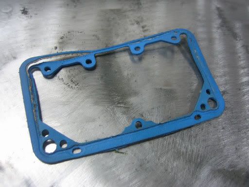
I definitely had to battle some fuel leaks before it was all wrapped up. The bowl fittings that came with the AED lines came with new gaskets. They looked the same as the ones that were on there already but I used the new ones. They leaked badly, like fuel dripping all over the place. I put the old ones back in and the leaks stopped. I'll also mention that the bowl gasket was completely split and was useless so I got a new one,
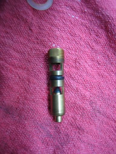
In thinking about pressure and float level, I researched a lot about what could cause this situation and I read over and over again that fuel could be pushing past the needle and seat or debris may be caught in the needle and seat itself. I took the needle and seat out and found that the o ring was hard and had a small crack in it. There was no debris lodged in it but the crack in the ring made me think that this may have been contributing to the high float level. Off came the bowl. I cleaned it up and installed a new needle and seat.
Thought I would also mention that during the initial set up, I broke a fuel bowl sight glass trying to set the float level. I had never dealt with a clear one before, just the screw in type. The glass sight on the Proform is held in by a snap ring and gets sealed with an o ring. I tried removing the sight while the bowl was still on the carb which can not be done. Really, its not necessary to remove it all since you can actually see where the float level is without moving the plug. Doh!
But I digress. So before I had this brilliant epiphany, there I am pinching that snap ring. I got the ring out but when I tried to get the sight out, it became cocked and got chipped. I had to call Quick Fuel (who makes the Proform bowl) to get a replacement. I got 2 for a total of $4.86. I managed to get the chipped on back in and it's not leaking at the moment. I couldn't wait to test out the new stuff and go for a ride. No way was I going to let a stupid chipped sight glass ruin it, even if it was a leaker.
Here are some pics to illustrate what I've been yammering about.
This is what I started with. You are looking at a 12psi fuel delivery system. Note air compressor pressure gauge in gauge port to fill hole where cowl gauge line was.
This is what I was imagining. Note generic parts store chrome dual feed line.
Steel line from pump to carb. More plumber's fittings and the dreaded teflon tape. Yes, I need a new dipstick, Jimmy.
Original fuel pump inlet and outlet. Its a leaker, Vern.
Underside.
Here is most of the stuff I ordered from Summit: line kit, hose, fittings, gauge, bracket etc. I had the regulator already from a Holley blue electric pump, came as a kit. Regulator is 12-803.
First step was to measure how long of a hose I needed and cut it to length. I took out the steel line and laid the hose on it. I added a few inches before I cut, just in case. Here is the hose cut with an end installed.
A pic of the completed hose.
Next was getting the line out of the pump. Here is a comparison shot of the two different outlet fittings. The black one is worlds away from the plumbing supply store fitting. We're not plumbing a sink here gang.
So I have a length of hose with a hose end and a fitting, let's stick it in the pump and see what we have. I used Russel teflon gel sealant for the pipe thread fittings. Works very well. Bye bye plumber's tape. here you might see how how clocking and angles come in to play.
Looking down to the fuel pump from above. Note how the hose end is right against the alternator bracket. that's where i used a rubber clip.
Hose is done and routed, on to the topside. Here's the regulator installed on the bracket. I tried mounting it right side up but the hose end was hitting the intake runner. The bottom of the regulator was also hitting the valve cover and crunching the alternator wires. It's OK to mount it upside down. There is plenty of clearance for the linkage with this bracket, i think it could have been made a little shorter to help clear the valve cover. Or maybe someone needs to come up with a Mopar-specific 59 degree head design.
Pic showing interference points. There was no way this was going to work, the lines would not match up and the angle of the thing was all wrong for this particular combination (small block, Victor 340). Perhaps it might work with different parts.
I called AED at this point. I asked if it was OK not to use the bracket and they told me it would be fine, only really high vibration situations require a bracket. Indeed, the steel lines are enough, it's totally solid. I might try to make my own at some point but I can roll with it like this for now. Here is the system without the bracket. I angled the regulator to match the angle of the valve cover.
Here it is with hose installed.
Couple other pics. First is the broken sight. Not sure how this isn't leaking but it's not.
Trying to show the crack in the N & S o ring. Hard to see but it's there.
Blown out bowl gasket. How the f*ck does that happen? Probably from sitting for long periods of time with old fuel. Wasn't me for once though...
Home made AN wrench. Now that I've done it, I would say it does pay to have one of those specialty AN wrenches, the anodized fittings get galled up pretty easily. I used this until I realized line wrenches work really well.
One more pic of the primo Russell hose and fittings.
Well hey, thanks for reading. Hope you found the writeup enjoyable and or helpful. I had a good time doing this, it was a nice project that didn't break the bank or have the car down for a long time. If you have all the parts, you could do this fairly quickly. The most time consuming part of this project was educating myself on all of this stuff and planning it out. I actually fixed a problem for once and stuck with it through some hiccups to arrive at a decent outcome.
- Greg


