Gauges and cluster light only work with lights on?!

-

Jimmycocopop

Well-Known Member
Joined
Sep 10, 2014
Messages
51
Reaction score
2
Location
St. Peters, MO.
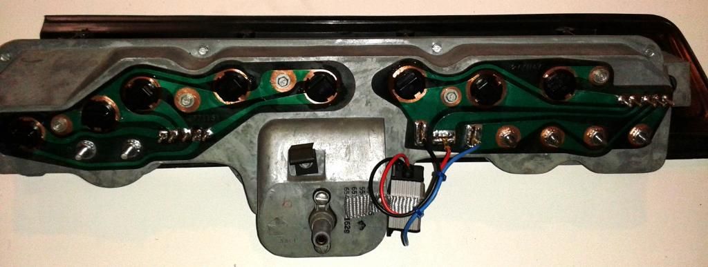
So here's one I haven't found in the forums yet....(73 Duster Base) Gas Gauge, & indicator only work when the headlight switch is pulled to ON :banghead: Each wire from the main harness is connected appropriately based on the wiring diagram. (Side note:Temp Gauge still doesn't work but I'm thinking it may be the sender....working on that later.) So I recently pulled the voltage limiter and did the 7805 regulator from radio shack with a separate capacitor to maintain the 5v. Worked great.....with the lights ON! Anyone ever ran into this problem? Looking at the service manual wiring diagrams now to check other connections.
 
So clearly i made a mistake in putting that the gauge lights only work when the lights are on.....duh....i meant the indicators and gauges only work when the headlights are on.
 
The first thing that comes to mind is a grounding issue. The cluster is originally "poorly" grounded by the mounting screws. Run a pigtail from one or two of the PC board ground screws long enough you can reach when taking it in/ out and bolt the end to your column support, etc
 
Thanks! I will give that a try!

Post back with results. Is the cluster still out? IF so, post a nice clear photo of the back

You may? have hooked your 7805 regulator to the wrong terminals on the cluster.
 
Post back with results. Is the cluster still out? IF so, post a nice clear photo of the back

You may? have hooked your 7805 regulator to the wrong terminals on the cluster.

Followed the instructions as found on several sites. Red wire is actually the ground. Didnt have any black wire. So it worked for a few minutes then the gauges went dead again. I also tried your suggestion with pigtail to column support. Any specific ground source on the back of cluster that works better than others?
 

Attachments

  • image.jpg
    89.6 KB · Views: 268
Pic after the new regulator/capacitor installed, with engine running and lights switch pulled on.
 

Attachments

  • image.jpg
    28.9 KB · Views: 243
You sure you have guages and indicator lights hooked to a switched constant 12 source and not to the headlight switch, headlight switch should only control illumination in the cluster not the actual guages
 
Followed the instructions as found on several sites. Red wire is actually the ground. Didnt have any black wire. So it worked for a few minutes then the gauges went dead again. I also tried your suggestion with pigtail to column support. Any specific ground source on the back of cluster that works better than others?

Either of the factory screws visible in this photo are ground. Hook (or solder) a pigtal to one of those points and run to a bolt / nut such as the column. Your "ground point" for the regulator could also work

Also, what was wrong with my 67 ( I still use a plug in IVR) is that the brass contact fingers were not making contact with the PC board. Those are what you used for connections

I recommend you solder directly to the PC board traces rather than the brass fingers. That might be your whole trouble

Use an xacto or even a "sharp" screwdriver to scrape down to clean copper. Use proper solder and tin the board trace, then make your connections. Try to be quick and don't overheat

Also, loosen / tighten the gauge nuts a few times to scrub them clean. They can be corroded even though appearing tight.

Have you inspected your PC board pins and soldered/ repaired them?

What are you using to ground the cluster during your tests?

Other than the above, get the shop manual / diagram, and test the PC board harness connector for proper ignition voltage, and right at your IVR connections to the new regulator
 
I was just a couple minutes to slow, 67dart273 just said what I was typing up!

May not be related to a direct wiring issue, but while your cluster is out, make sure you remove, clean, re-tighten (or replace) the nuts to the back of the fuel/temp gauges. That was the issue for both my 69 & 71 darts. The gauges were intermittent due to weak connection.

I actually read a bunch of posts prior to all this and checked all the wiring from point to point as 67dart273 has suggested many, many times, haha. He and alot of other guys have great info! Thank you to to them!

Great job on the voltage regulator also. I ended up buying one on ebay for 25, works great.

After I figured out my aluminum nut issue, I decided to take out the cluster again and fully clean everything.
1. Soldered all pins & the 3 slots for the limiter since those are pretty weak areas.
2. Replaced the aluminum nuts with the type that have the star washers attached to grab a bit better. (Got them at Ace).
3. Cleaned all the contact points for the lights. (Used a brass wire brush very carefully).
4. Put a little dielectric grease on all the connections to help with connectivity and corrosion.

Everything works great now!

http://i1218.photobucket.com/albums/dd420/adcowen/20140830_190425_zpsf05ab65d.jpg
 
Thanks for all the great advice everyone! Looks like I will have some work to do! Unfortunately it will have to wait for the weekend...out of town for work this week. But I will post more pics and updates as I move forward. I am determined to get this right!
 
So you did get it working and solved the problem? Good job
 
I've always had good luck with a 7805 regulator. It's simple and reliable when hooked up correctly. The only drawback is that it's not quite as fast as using a pulse regulator. I also add a tiny LED to the 5v output so I know it's on and working at a glance. As for your RED wire for ground.... I'm still cringing!
 
Update on the Duster.....cleaned all copper behind the cluster and cleaned and soldered pins. Soldered pigtails to ground on cluster and ran to steering column for additional grounding. Replaced fuses, replaced temp sender, replaced all bulb sockets and bulbs, connected everything up, all lights work, temperature gauge now works, but fuel gauge still dead. Checked voltage and ground at sending unit, multimeter read 5. Checked at gauge post, read 4.2-4.5, but no movement of the needle....so I'm guessing the fuel gauge itself is toast?
 
What happens when you ground the sender stud of the gauge? Should "head" right up to full immediately, "key on" of course.

While doing so, check voltage on limiter side stud of fuel gauge, "right on" the stud. Should have your regulated 5V present there.

Final test would be to connect at least one 1.5 V battery directly to the gauge and see if it moves. Remove the sender and 5V connection before doing so
 
Have not ground the stud but I will try that tonight. As far as voltage, everything reads between 4.5 and 5 at all the points on the cluster and at the sender. So power seems to be flowing as it should to where it should. More to come later.
 
what is that black square in the picture of post #6, the one with the 3 wires coming off ?? Can this be bought anywhere ? one of the wires has pulled off of the one on my car ...
 
what is that black square in the picture of post #6, the one with the 3 wires coming off ?? Can this be bought anywhere ? one of the wires has pulled off of the one on my car ...

The small black square is a chip voltage limiter. You can pick one up at Radio Shack for a couple of bucks. Replaces the original voltage limiter that evidently tends to fail.
 
What happens when you ground the sender stud of the gauge? Should "head" right up to full immediately, "key on" of course.

While doing so, check voltage on limiter side stud of fuel gauge, "right on" the stud. Should have your regulated 5V present there.

Final test would be to connect at least one 1.5 V battery directly to the gauge and see if it moves. Remove the sender and 5V connection before doing so

OK....so grounded the post at the fuel gauge and no $#*+ it pegged the needle. Plugged everything back in, each post with power had 4.95v, but the fuel gauge only read 4.21. Same reading at the pin (blue wire). I feel like there is something simple I'm missing here.
 
Here's something you need to keep in mind. Your multimeter draws a TINY TINY amount of current. Let's say the circuit is "good" up to and including the gauge, and somewhere between there and the tank, "you have a problem."

(This is an example)

Picture in your mind "where this goes." Each numbered item is a potential problem spot

1.....From the gauge stud, the stud and nut must make good connection to the PC board

2.....The PC board must be "good," that is the trace not cracked or burned up

3.....The PC board trace must be making a good connection with the harness connector pin

4....The harness connector (on the wire side) must be making good connection with the pin

4a..The harness connector terminal must be making good connection with the wire

5....The wire leads down to the left kick panel connector going to the rear, and so once again we have

5a.....the connection between the wire and the connector terminal

5b....the connection between the two mating connector terminals

5c....the connection between the mating connector and the rear wire

6.....the connection between the wire to the tank and the molded end connector

And.......we haven't even brought the sender, the gauge, or anything other into the picture.

Now if ANY of the connections above are a poor, corroded or loose, "high resistance," they could be conducting enough to show voltage on your meter, but when you ground the tank wire or connect to the sender, the ADDED CURRENT the completed circuit is attempting to draw will cause all voltage in the system to 'drop' across the high resistance connection.

HOW DO you find it?

Take your test resistor. Confirm that the gauge works "at the gauge." Then just keep stepping the resistor connection "towards the rear" one point at a time in the above numbered positions.

Sometimes, it's easier to access, and saves time by "leapfrogging"

Say you get into the kick panel and probe there and no gauge movement. "Might be" right there in that connector. Where was it good? At the gauge stud?

Ok, what's in between.........? Why the PC board harness connector. Check there. Wiggle it Good? Bad? etc.
 
Well put, great info! So far I can rule out the sender at the tank....5v, connector @ kick panel...5v. Only thing I haven't checked is between the kick panel to the fuse box, and from the fuse box to the cluster. Hopefully I can wrap this up over the weekend. Thank you for your support and walking me through this.
 
-
Back
Top