HDK Bump Steer 101

-

HemiDenny

HDK Suspension
FABO Gold Member
Joined
May 31, 2006
Messages
8,652
Reaction score
3,950
Location
NW Ohio
Since I posted the HDK "no camber change" photos on this site
there have been numerous queries regarding bump steer readings
on the HDK.

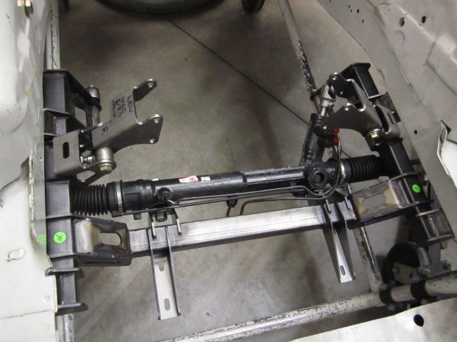
This week, I fitted a new power steering rack equipped HDK into
a mock-up rig to take some measurements.

BumpSteerBasics022_zpsb7adbc05.jpg

BumpSteerBasics003_zps3e68b814.jpg


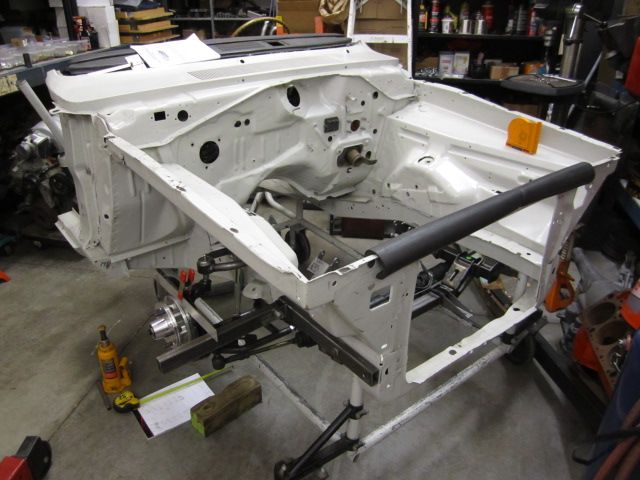
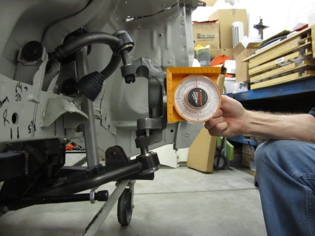
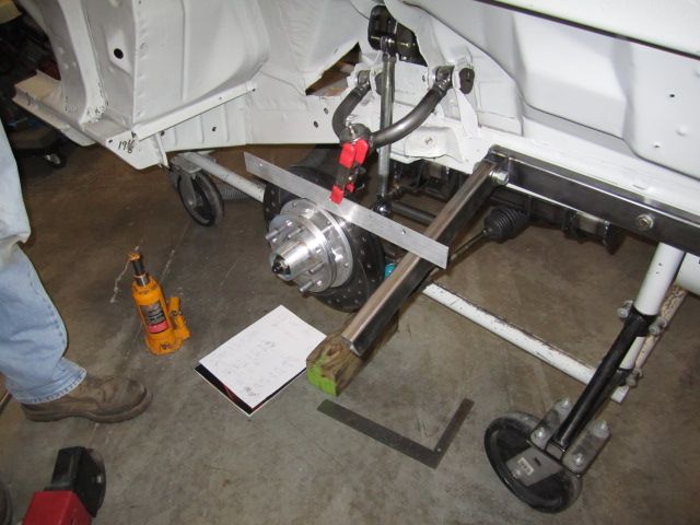
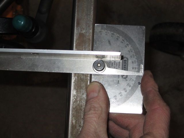
I bolted an adjustable reference arm to the RF unit body rail and
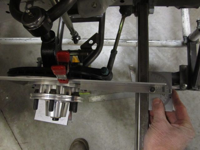
clamped a straight edge to the surface of the brake rotor. Then
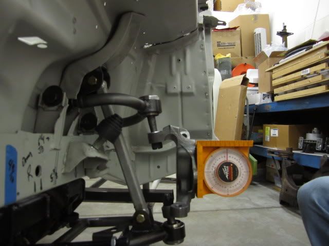
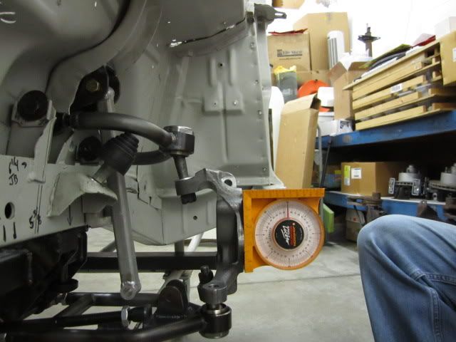
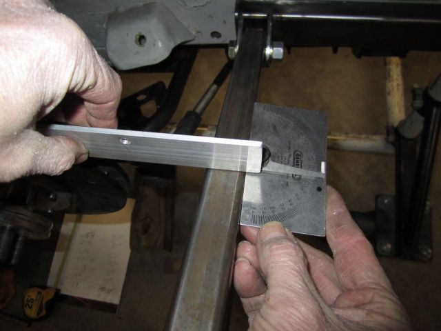
with the suspension at different compression heights, I used an
angle guage to measure the tow change (bump steer) at all points
throughout the suspension travel.

BumpSteerBasics013_zps4e18a41c.jpg

BumpSteerBasics005_zps7c573c17.jpg


The result? Virtually no toe change at any point in the suspension travel arc
of from 10" compressed to 15.5" fully extended (5.5" at the shock which
equates to 6-7/8" at the tip of the spindle).

BumpSteerBasics018_zps5b55cd45.jpg

BumpSteerBasics010_zps7096aed3.jpg
 
This is really good info. Could you re-post the camber change pics again?
it looks like they belong here with these as well.
 
Here you go........


The art of suspension

With no bump steer, proper ackerman and almost (now) 6" of travel,
watch the camber change (it doesn't):

Fully compressed - 0 degrees


degree1_zps4fb72701.jpg


Now at normal ride height - 0 degrees


degree2_zps8509b143.jpg


.......and finally fully extended - 0 degrees


degree3_zpsddfc51c5.jpg

 
Drag Racing????? That's Golden for the twisties and anything else you want to throw at it-Denny has gold on his hands and I'm glad to have donated to the cause--LOL--Swifter
 
That's the kind of proven geometry important to know when
considering a major purchase. Thanks for posting.
 
It would be nice to see the results from other kit mfg's (anybody?) but
I am certain that I have found the answer to my needs right here.
 
....

The result? Virtually no toe change at any point in the suspension travel arc
of from 10" compressed to 15.5" fully extended (5.5" at the shock which
equates to 6-7/8" at the tip of the spindle.

....

How much is virtually no toe change?

I think people not familar with this, might not have a feel for how many inches is significant and not significant.
 
in degress..... is how I measured. That said, the guage did NOT move off the 90* mark...."virtually" for me is less than a small fraction of a degree.....unmeasurable with the equipment I used.

Initially took the measurements myself with a little disbelief, I felt it would move somewhat when fully compressed or fully extended. I called OldManMopar to have him stop by to photograph and verify the results to me.

to answer the informational question....
I will turn the steering to simulate 1* of toe in and measure in inches and post the result.
 
Thanks Hemidenny.

Onig

no...thank you for asking! You were not the first, but it made me realize I needed to place this info at the top of the list.

Mopar to ya'
Denny
 
Looks like a great set up for drag racing!

I agree....

for drag racing NO bump steer (toe change) when those front wheels drop is the KEY to high speed stability AND better ETs with less tire scrub. And please do not forget, the 30+ pound weight loss.....BTW, did I mention and often overlooked, my set-up is considerably less $$$ than the other guys?

I think some might not have understood the point of your question. Thank you for your astute observation.

another Mopar to ya' (thanks)
Denny
 
It would be nice to see the results from other kit mfg's (anybody?) but
I am certain that I have found the answer to my needs right here.

You mean objective results in the form of precision numerical measurements?...


Sure. Here's one I did with a standard Longacre bump steer gauge that measures to the .001" with a digital dial indicator at 7 1/2" out from the center of the bolted hub held level with a bubble gauge.
 

Attachments

  • Copy of IMG_3582.jpg
    72.4 KB · Views: 605
  • CorrectedBumpSteerChartLFInitial.jpg
    89.2 KB · Views: 595
You mean objective results in the form of precision numerical measurements?...
Please do not misquote me sir but I would welcome any information offerred.

Ultimately I'll make my own determinations but I am completely satisfied with what I see here.
 
Will be looking foward to the early "A" K when it hits production.Great products you have.
 
The Longacre Bump Steer guage has been around forever and is a
handy and useful tool that can be used in any home shop.

http://www.longacreracing.com/catalog/item.asp?id=155&catid=5

The assemblers of the HDK's, Streicher Racing (builders of the Hawk
USAC Midget) very well may have one. Denny eats lunch with these
guys most every day, so it's possible that one could be available to
take a "precision numerical measurement" as you put it.

I do know that I observed the whole process closely and the guage
appeared to not vary at all.....of course a digital dial indicator would
be more accurate than my aged eyes.

http://www.theracedepot.com/product7.htm
 
You mean objective results in the form of precision numerical measurements?...


Sure. Here's one I did with a standard Longacre bump steer gauge that measures to the .001" with a digital dial indicator at 7 1/2" out from the center of the bolted hub held level with a bubble gauge.

Very nice......it seems now, you already know the answer to your question being very knowledgeable and certainly no rookie.

However....I used my antique / old measurin' tools to try to give you (and others) a fair answer to your questions.

I measured 13", not 7.5", from the center of the spindle, so my numbers are a little strong. I figured that to be outer edge of a 26" tall tire. Honestly, many but certainly not all set-ups appear to be moving / bumpsteering so much that you can easily see the movement with your eyes.

Here are the results....

If it was off by
1* is .....3/16" or .1875 off center
2* is......13/32" or .40625 off center
3* is......5/8" or .625 off center

I might add, mine was not off 1* or 3/16"....it wasn't even off a single 16th.

There ya go!....I think that is what you were after.

Someday, I might get an bumpsteer guage that measures that precise. They look nice and do a hell of a job. I will have to put it on my wish list.

BTW...those are some trick uppers on that ride, they sure have a lot of ball joint sleeve angle on them. why so much? (just wonderin', must be for road course set-up)
 
very nice......it seems now, you already know the answer to your question being very knowledgeable and certainly no rookie.

However....I used my antique / old measurin' tools to try to give you (and others) a fair answer to your question.

I measured 13", not 7.5", from the center of the spindle, so my numbers are a little strong. I figured that to be outer edge of a 26" tall tire. Honestly, most , certainly not all set-ups appear to be moving / bumpsteering so much , you can easily see the movement with you eye.

here are the results....

if it was off by
1* is .....3/16" or .1875 off center
2* is......13/32" or .40625 off center
3* is......5/8" or .625 off center


there ya go!....I think that is what you were after

Someday, I might get an bumpsteer guage that measure that precise, ....they look nice and do a hell of a job. I will have to put it on my wish list.
...

No question that is not a lot of bumpsteer in your HDK. Especially at 6" compression and 5"? extension. Really good at those high travels! Even though you didn't measure to the thousandth of an inch or the hundreth of a degree, it's still really good even factoring measurement +/- tolerances.

But I was just afraid someone reading this would assume you had .000" toe change or .00 degree toe change. Then see some other suspension with .040" toe or .05 degree change and think that was bad. That's not a fair comparison because one way records smaller measurements than another.

Now if something else was 1.82 degrees or .575" bumpsteer, well that is a 1/2"+ more than what Hemi Denny measured.

People in this thread are trying to draw comparisions to other K-members, kits, and suspensions. Nothing wrong with that. But please just compare apples to apples or put things in the same apple level.
 
....

BTW...those are some trick uppers on that ride, they sure have a lot of ball joint sleeve angle on them. why so much? (just wonderin', must be for road course set-up)

They just did that to replicate the factory upper control arm ball joint angle. It just keeps the ball joint sleeve closer to perpendicular from the spindle at ride height. Some compensation for the tilt the anti dive angle put on the upper control arm.

Nothing to lose sweat over, IMHO.

It really doesn't matter. Because that angle from the side view doesn't change enough to over extending the angle of the ball joint stud to the sleeve. That angle doesnt change much at all. And an upper ball joint tilted a little is fine. That why it's a ball joint.
 

Attachments

  • Hotchkis7_26_10TVSbuildSm34.JPG
    92.3 KB · Views: 532
-
Back
Top