rapidtransitric
LX/LC platform a body swap pioneer
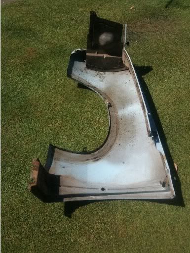
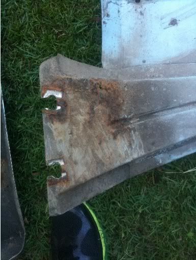
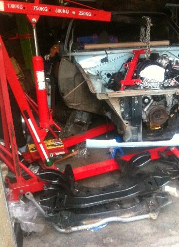
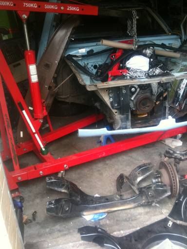
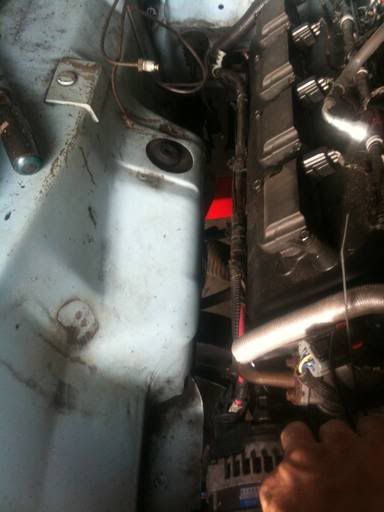
you'll have to notch the passenger side rail/ apron for alternator clearance
Maybe I'm wrong, but if your car is right hand drive, the motor should be offset to the left, maybe you need to switch the mounts around (left on the right & vice versa )
Maybe I'm wrong, but if your car is right hand drive, the motor should be offset to the left, maybe you need to switch the mounts around (left on the right & vice versa )
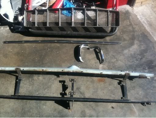
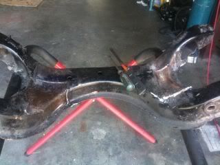
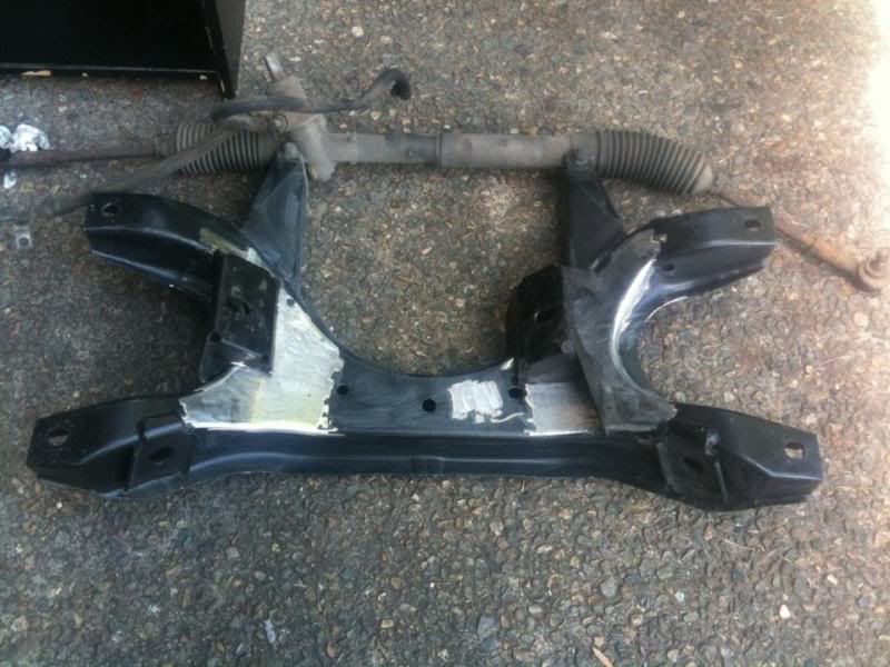
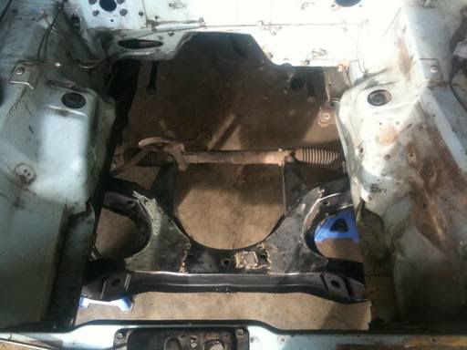
Mounted in the carThose mounts for the rack - are they commercially available to must be fabricated. If commercially available - from PP&R, Queensland, or ??
Mounted in the carThose mounts for the rack - are they commercially available to must be fabricated. If commercially available - from PP&R, Queensland, or ??
They don't sell the fin's (thats what I call them) that you bolt your rack to. It's a k-member exchange basis. I assume it wouldn't be too difficult to replicate though but it's something you'd want to make spot on for your suspension to remain in check.
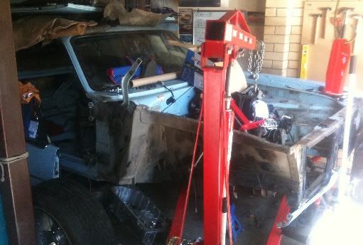
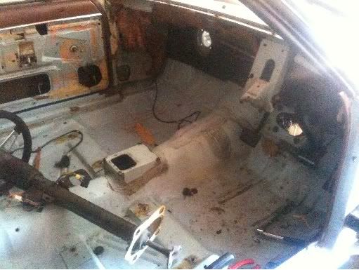
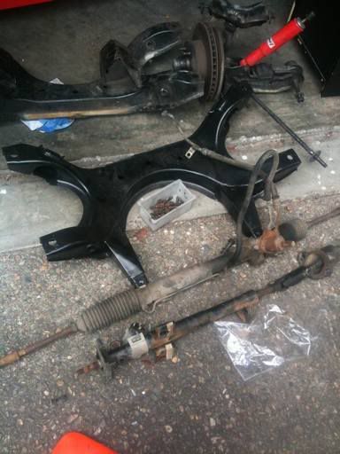
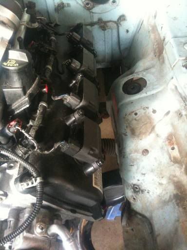
Mounted in the car
They don't sell the fin's (thats what I call them) that you bolt your rack to. It's a k-member exchange basis. I assume it wouldn't be too difficult to replicate though but it's something you'd want to make spot on for your suspension to remain in check.
The rack-n-pinion is it an OE part? Are the K members available as well. I can't imagine that not working on a US car. Hmmm.
Thanks
The rack-n-pinion is it an OE part? Are the K members available as well. I can't imagine that not working on a US car. Hmmm.
Thanks
Well the rack is itself is off a Holden Commodore VR (around 1994). There are many the same dimensions though, the bolt holes for the rack are 42" center to center.
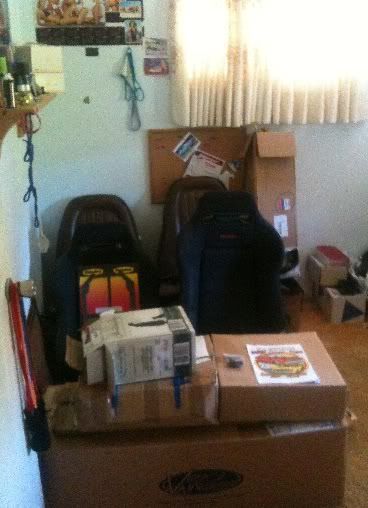
What size wheels did you have on it mate?? I had 16" Torq Thrusts but now that the car is basically a shell and I'm rebuilding it completely thought of getting 17"
Really cool build. I love the Australian Chargers. Looks like you got another there too...1971 or 1972?


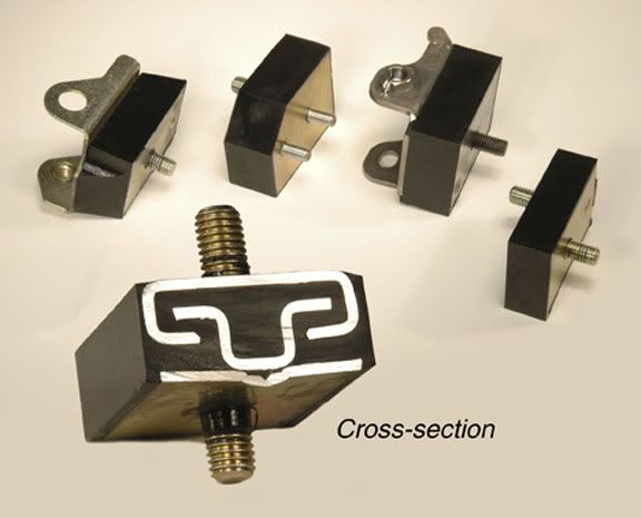
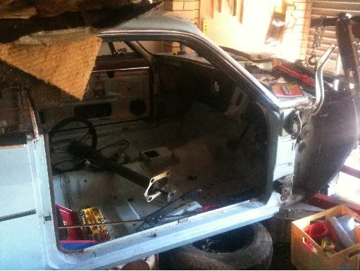
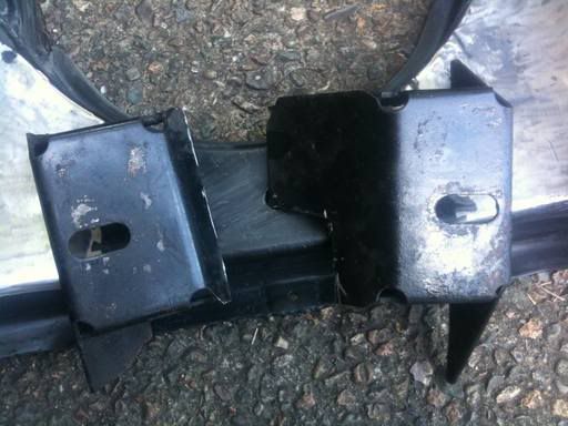
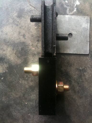
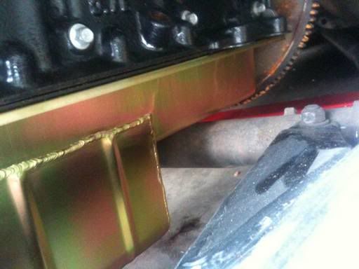
 Rough mock up of what the final transmission mount looked like. I ended up cutting the lower part to half the width shown here to gain some ground clearance.


