Modernized Engine Wiring

-

BillGrissom

Well-Known Member
Joined
May 10, 2009
Messages
8,131
Reaction score
1,037
Location
Sacramento
As promised, details of how I modernized the engine wiring in my 65 Dart 273. Glad to answer questions.

I got a Power Distribution Center (PDC) from a 95 Jeep Grand Cherokee. I expected the relay terminals would be Packard 57 type, but were a variant of the square Ford type. I found the ones for the small fuses (left in 1st photo), but only ones too thick for the relays (middle) unless squashed a bit. I ended up splicing to existing wires, rather than new terminals on new wires. I suggest cutting as much harness as possible. I ended up removing all wires from the PDC and starting from scratch since existing wires were the wrong size or branching.

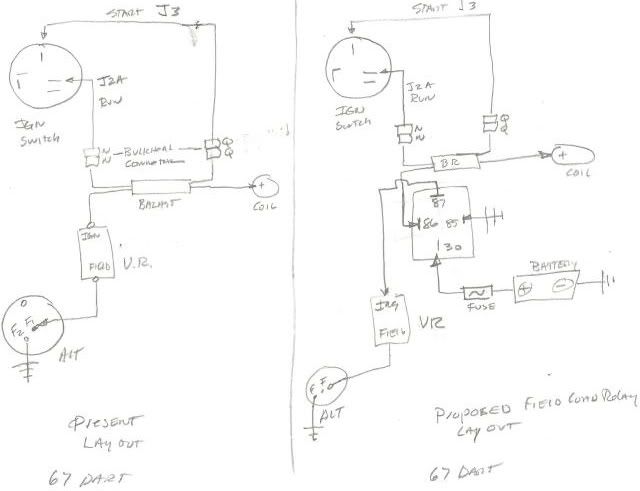
The PDC eliminates all relays on the firewall, plus adds relays for high/low beam, ignition, and fuel pump. I put the voltage regulator beside the alternator (2-field wire type). I ran wires in smooth PVC sheath (SPC Tech), which is easier to clean than split loom, but you must pull the wires thru. I used 20 awg ribbon cable for most wires to the bulkhead since they simply actuate relays. I saved my existing wires by pulling out the 57 terminals (right in 1st photo) and crimp+soldering on new ones. Note how you squeeze longitudinally to remove them. I used the light harness from a 74 Dart, which adds a ground wire. I had to reuse my bulkhead connector housings since the 74 Dart's are different. I don't have the 3rd connector since my wiper wiring is under-dash.

The power wiring requires the most explanation. My 65 Dart has large lugs for power leads, so no concern with melting spade terminals as in later years. Interestingly, my 64 doesn't have those and runs the leads thru a grommet hole (at least someone did). I ran 8 awg from the battery to the "BATT" lug, w/ two 12 awg on the dash side, one to the ammeter and another for future loads like a power seat. Ideally, all current from the battery flows thru the ammeter to be measured. Of course, not the high starter current and the factory didn't meter the horn or starter relay currents.

The alternator supplies the PDC, then a 12 awg wire runs to the "ALT" lug. Under-dash supplies branch from there before the ammeter. I installed the later square-back alternator, which supposedly outputs 70 A. Since that could fry my ammeter and wiring, I shunt extra current to the battery, bypassing the ammeter. I use two parallel diodes (Vishay VS-175BGQ045), soldered back-back. They are rated 170A, but more important is that they have a good heat sink. I bolted them to my Battery Brain as shown (under silicone tape), which is much copper going to the battery as a heat sink.

For the diode design, I first measured the drop across the power lugs in my 65 Newport as 0.72 V at full scale (full field on alternator). Silicon diodes have about that forward drop, so seemed a good fit. In the Dart, I measured 30 A at full-field (external ammeter). My ammeter then read ~1/5 scale and I measured a 0.25 V drop across the diodes. The manufacturer's plot shows ~20 A thru the diodes at that drop if 70 F, so ~10 A thru my ammeter. The power dissipated in the diodes would only be 5 W. If I could get 100 A output from my alternator, the diodes would drop ~0.6 V, my ammeter would read almost full-scale and the diodes would dissipate ~45 W, probably warm but not super hot. Had I rev'ed the engine I might have seen more output. I have fuses on all power leads, at least 80 A, mainly to protect from a dead short.

You can read elsewhere about the Battery Brain. I started putting one on all my cars 3 months ago and they already saved me from being stranded a few times (those batteries tested bad later at Autozone).

On the dash harness, I just repaired all the prior hacks like butt crimps, missing turn signal connector, and added an ACC relay. I put runs in split loom since the factory wrap was gone.

It all looks simple when done, but weeks of work. Don't imagine you can do similar in an afternoon, and no I am not soliciting to work on your wiring. I limit my effort to offering encouragement only. Enjoy, take pride in your A body, and don't be a hack.
 

Attachments

  • PICT0002.jpg
    99.6 KB · Views: 1,176
  • DSCN0672.JPG
    187.9 KB · Views: 1,140
  • PICT0010.jpg
    92.7 KB · Views: 1,155
  • PICT0003.jpg
    80.3 KB · Views: 1,115
  • PICT0009.jpg
    61.9 KB · Views: 1,086
  • Vishay VS-175BGQ045.jpg
    4.5 KB · Views: 1,199
WHOA! Big job. Ya got balls where I don't for this mess. I'm going to try and re- wire up my Duster with a kit, but this, THIS is something else.
 
I used a smaller relay box out of a 90's Voyager, same idea. In my 67, I "tossed the towel," converted the ammeter to volts, and ran a nice big no6 right from the alternator to the start relay. Bulkhead is all bypassed.

Bill I don't understand exactly what you did, there with the diodes. You said "back to back," did you mean parallel? I do understand how external shunts work, I just didn't catch how you did this.

Draw us a diagram, maybe?

Thanks.
 
67Dart273;1720439 Bill I don't understand exactly what you did said:
Sorry, "back-to-back" wasn't the best description. The diodes are in parallel, facing opposite directions, so one is in the forward direction for flow either from or to the battery. The ones I found on ebay (photo) nestled together nicely to bench solder together. I then filed the holes clear for a #10 screw.

You might use the stud-type diodes that have wire cables. I didn't see a good way to mount those in my setup. You would need to electrically isolate all exposed metal since at battery voltage so you wouldn't want a wrench brushing the metal. My first thought was to put diodes across the firewall leads but harder to dissipate the heat there, plus would have to run 8 awg wire to both sides.

A final comment on conductor sizing. Many people think 12 awg = 20 A max, from their knowledge of home wiring. That rating is for wires buried in fiberglass insulation, and the concerns of burning down a house. In a car, the "appliance rating" is more relevant. I recall that is more like 40 A for 12 awg.
 
Diodes--I see so you are using the forward drop in each direction to form a wiring shunt.

So far as wire ampacity, I resist the temptation to over-rate smaller wire. After all, wire (in cars) isn't all that long, and therefore is not all that expensive. Voltage drop figures in vehicle wiring should be held much tighter (percentage) than 120V/240V building wiring

Besides, after fighting for years with Mopar "small wire" in tail lights (adding a trailer!!) the bulkhead connector, and the "was always" too light headlight wiring, I'm more than willing to "not downsize" wire gauge.

A good example of this was my old 70RR, which had 4 tail/ turn lamps, and I did do some trailer towing. So you have 4 stock trail lamps, plus the clearance and trail lamps on the trailer --all run off the flimsy stock Mopar wiring.

Over the years, most of my old RR got re-wired with nothing smaller than no14. I had lots of it.
 
So why not just a straight up shunt? Why piss away .7v in a diode that can fail?

B.
 
So why not just a straight up shunt? Why piss away .7v in a diode that can fail?
B.

Valid concerns, since if the diode opens, all current goes thru the dash and ammeter. However, I fuse those to protect them. Not sure what happens to the alternator if open-circuited, but I suspect it wouldn't hurt it. If it did, an alternator is easier to replace than the instrument cluster. Diodes usually fail in short-circuit, though mine does have a series fuse.

You need to design conservative, which is why I used 170 A diodes. But you have to know what that rating means. At any current flow, you must calculate the power dissipated in the diode and how hot it might get. I think "170 A" means the current at which it will have the "0.7 V standard silicon drop", but someone can research.

A diode is much better than a fixed wire resistance because the diode resistance drops as the current increases. If a wire, the resistance would increase with current, due to the heating. The ideal diode to use would break-down at 0.7 V (where ammeter hits full-scale) and conduct all current beyond that to hold 0.7 V. This would be similar to a "pressure relief valve" in plumbing. Your fixed wire resistor is more like a fixed orifice in plumbing. There are such diodes termed "zener" (used in reverse bias), but I haven't seen any that could handle these currents. That is why I rely on a forward drop.

I wanted to keep my ammeter since I hated losing that in my 80's cars, and got stranded a few times because of the useless battery warning that only lit when too late. I don't care that the ammeter is accurate, I just want to know if charging or discharging, plus I feel better when all gages in the dash are functioning. I do have a voltmeter, a portable one I plug in the cigarette lighter ($15 Amazon). I find those invaluable in my newer vehicles that give no other charging status.
 
So why not just a straight up shunt? Why piss away .7v in a diode that can fail?

B.

Actually, a shunt "pisses away" some voltage. The Ferds and Chryslers I've worked on actually used the narness itself as the shunt. In other words, the "ammeter" was actually measuring the voltage drop across the charging harness. This means you cannot "upgrade" the harness to a larger size without making the "ammeter" ineffective, something that many of the Ferds suffered from, anyhow.
 
Uh guys I know quite a bit about diodes - and shunts.

The two problems are where you source your reference voltage from, and what happens when that fails.

Since you are not running a remote sensing regulator on your alternator, your sense voltage is not actually battery voltage. You can wind up undercharging the battery.

If only one of those diodes fails open you have other issues as well.

losing the voltage reference to the alternator has the same effect as removing the positive cable from the battery...

Finally, every rectifier I have ever tested increases voltage drop under load - it does not decrease. The voltage drop does decrease as the diode gets hotter, but that thermal gradient happens with or without load based on case temperature. See your device data sheet, Figure 1:

http://www.vishay.com/docs/94582/175bgq04.pdf .

The OEM system has two big resistors already that should go straight in the trash - the fusible links. Replacing the 16 gauge link with a decent circuit breaker should be job 1.

I am convinced that Mopar went with the low bidder on electrical... and the high bidder was Lucas. All of the wire gauges are undersized, protection is lacking, and now that the systems are 40 years old they are a fire hazard.

B.
 
Since you are not running a remote sensing regulator on your alternator, your sense voltage is not actually battery voltage.

My Vreg sense is IGN, just as in the factory design. I imagine that if you hooked that directly to the battery you would run down the battery when the car is off.

The diodes are a parallel path around the ammeter. They are not an additional series element in the path from IGN to battery. The diodes decrease the resistance in the path to the battery.

Finally, every rectifier I have ever tested increases voltage drop under load - it does not decrease.

You are confusing voltage drop with resistance. Resistance is the voltage drop divided by the current. They don't usually plot that for diodes because it isn't even close to a constant ratio with current. But if you do plot it, you will find that the resistance drops as current increases, unlike a wire shunt. That is good for this application.
 
Besides, after fighting for years with Mopar "small wire" in tail lights

I haven't noticed a problem with headlamp brightness by using the 74 front lamp harness (16 awg?). It does have a dedicated ground wire instead of the "at lamp" body screw in my 65 harness. I suspect most problems are more from corroded connectors rather than too small wires.

My 65 Newport has a bunch of rear bulbs so I used LED's for some to decrease current draw and add reliability, even if not as much light output. I expect that with future LED bulb choices any under-sized rear wiring problem will go away.
 
My Vreg sense is IGN, just as in the factory design. I imagine that if you hooked that directly to the battery you would run down the battery when the car is off.

The diodes are a parallel path around the ammeter. They are not an additional series element in the path from IGN to battery. The diodes decrease the resistance in the path to the battery.


You are confusing voltage drop with resistance. Resistance is the voltage drop divided by the current. They don't usually plot that for diodes because it isn't even close to a constant ratio with current. But if you do plot it, you will find that the resistance drops as current increases, unlike a wire shunt. That is good for this application.

Not confusing anything. Open the link. Read the plot. Voltage drop on one axis, current on the other. Pretty straight foreward. It does not get better with more current. Period.

.
 
Not confusing anything. Open the link. Read the plot. Voltage drop on one axis, current on the other. Pretty straight foreward. It does not get better with more current. Period.

.

You're right but I don't see that it matters. even a COUPLE of volts, if the harness had that much drop, would be compensated for by the regulator.

The BIG enemy is HEAT, mostly in the infamous, original, bulkhed connector.

Hell I managed to burn the first one of those up in the early '70's long before Al Gore invented the internet. My 70 RR was supposed to have an "optional" 60/65 amp alternator. Both the original owner and myself were radio amateurs, and both of us had some gear in the car. Back in those days, "solid state" ham gear was either not real popular, or real expensive.

I used to run some VHF/ UHF gear, known un-affectionately as "GE TPL" ("Toilet Paper Line) which had a 60-80W output PA on 2 meters. On top of that I had an old GE "pre Prog" receiver and could work full duplex between UHF and VHF on the local San Diego repeater, which, interestingly, is still online today, WB6WLV.

http://www.wb6wlv.com/

GE "pre Prog," so named "after the fact" because it was made BEFORE (pre) the "Progress Line." Huge, Heavy, and a Watt Waster. Tubes. Vibrators

From here:

http://www.wb6nvh.com/GE/GEhist1.htm

GEPP002.jpg


and the hated "TPL" "Transistorised Progress Line", or "Toilet Paper Line." I made a latching relay control for RX/ TX channel selection--they used crystals, remember? and mounted it in my ashtray. Had a handset which hung on the dash. The girls in Pacific Beach thought I was a "narc."

TPL8.jpg


But enough. Things happened, and things smoked. So I looked around, and there it was, just like on the MAD electrical site -- melted bulkhead connector.

So, we get out the much-notated 70 shop manual (which I still have!!) and ran some new wires in thar.

One wonders how the many police cars of the day got through this.
 
Well, '273 it does matter. If you have the theory backwards, you may have made other mistakes...

If someone rolled in here to FABO saying that increasing compression reduced detonation, you guys would be on him like white on rice. If the rebuttal was that you had "confused detonation with pre-ignition" You would throw the BS flag.

Using a rectifier there is an over complication, and a potential failure point. My question was "why?"

I hung many Motorola Motrac radios in cars in the 70's. We never got near the OEM electrics, running a 4 gauge wire straight from the battery to the trunk. The headlights would dim when you mash the pickle and pound 135 watts into that antenna. Mopars were bad, but the Matdors were worse.

Any regulator can be referenced to battery voltage, but some are easier than others. All internally regulated GM alternators have a remote sense circuit and connection built in. Most Nippondenso internal regulators do as well. Ford 3G / 4G / 6G alternators all reference through the "A" wire which is constant B+ connected.

To battery reference the simple mopar regulator all you need is a relay. Run a 14 gauge wire from the battery, through a 20 amp fuse (to reduce voltage drop) and through the relay to the regulator. Trigger the relay with the ignition circuit. Simple.

B.

I don't get what you are getting at here?

How is it (again?) that Mopar regulators are NOT referenced to the battery? The only way that they are NOT is if/ when the harness drop causes a mis-reference. And ---- I most certainly have ALREADY suggested to some that they use a relay for the ignition/ regulator circuit. I do so in my own Dart. The fact that the harness has or develops drop does not mean they are not voltage referenced, it only means that the harness is poorly designed, or damaged. It most certainly was the INTENT.

And what? again is the theory that I have backwards? I think you may have misread something I posted.

So far as your 135W radios, I find it really difficult to believe that in the cars with full current ammeters, you didn't have problems. Don't forget that the C barges were the first to implement external shunt ammeters. Seems to me that came around about 71-72 or so in some of the models.
 
'273:

I did not mean that you had the theory wrong - you in fact agreed with the diode's increased voltage drop under load. I was referencing the OP's failure to understand the voltage drop. Sorry if I was not clear.

A direct reference between the regulator & battery does not exist in the mopar system. it sees the voltage drop through all of the bad connections, undersized wires, fusible links, etc. We both know how often an overcharged battery happens. If you have detailed a relay dedicated to the voltage regulator, great. Please keep telling people to do so.
I actually do regulators & related components for a living, and the regulator sensing path is still a ball of snakes today. Toyota / Nippondenso actually runs a dedicated circuit all the way to the alternator for sensing. Many medium duty GM trucks do too, especially if equipped with a lift gate.

we dropped those radios in brand new cars. The ones those idiots did not wreck were usually re-sold in two years back then, and were on their second transmission. Honestly the bulkheads may have been starting to melt, but the cars had so many other problems it was overlooked. They blamed the radios for everything anyway, including the unit with the fan blade stuck through the battery case. I don't miss most of that.

B.
 
bohica2:
To battery reference the simple mopar regulator all you need is a relay. Run a 14 gauge wire from the battery, through a 20 amp fuse (to reduce voltage drop) and through the relay to the regulator. Trigger the relay with the ignition circuit. Simple.


You rase an interesting point B that I hadn’t considered when making this modification last month. I think I have a 10 amp fuse, and smaller wire gage from relay to voltage regulator. My thought was 16 gage would be sufficient from relay to regulator where the run was only about 14 inches.

I’m going to reassess my wiring method based on your suggestion.

For those of you that are trying to picture this modification below is a diagram of how I did it. My 67 has electronic ignition, single ballast, remote Madd like voltage sensing at starter relay, and bypass feed from alternator to starter relay.

This modification has normalized voltage values under the hood for the first time since getting this car four years ago. Addressing bad connections, and replacing bulkhead connector & conductors with new only partially fixed an over charge, and or voltage drop problem. Cutting out the ignition circuit’s bucket of snakes someone referenced earlier did the trick.

I can post photes of where additional relays were installed to complament the charging circuit upgrade if anyone wants to see them.

Chargingcircuitrelayupgrade.jpg
 
'273:
I did not mean that you had the theory wrong - you in fact agreed with the diode's increased voltage drop under load. I was referencing the OP's failure to understand the voltage drop.

You are arguing with words you put in the OP's mouth. I never said the voltage across the diode drops with increasing current output. In fact it increases, just not near as fast as it would for the wire shunt you suggest. I said that the (effective) resistance across the diodes decreases with current output, which is good. The ideal diode would start breaking down at 0.7 V and hold that voltage drop as the current increased further, acting like the perfect "pressure relief valve", but I challenge anyone to find such a component that would work at these high currents.

I already answered your question about referencing Vreg in the wrong place. I still have the factory-designed path thru the ammeter to the battery. I just added an additional current path that bypasses the ammeter when needed.
 
A diode is much better than a fixed wire resistance because the diode resistance drops as the current increases.

Here ya go, hero, your own words. Wrong, just plain wrong. Look at the chart from your own component.

The voltage drop across that diode increases as current goes up. They all do. For an increase in voltage drop, you need an increase in resistance.

The diodes are your choice. They are not any better than a proper shunt. What you want to do with your own car is your business. I did not put a single word in your mouth. You invited questions in the first post, and I asked one.

Good luck with your project.

B.
 
For an increase in voltage drop, you need an increase in resistance.
Incorrect.
V = I*R. If R is constant (i.e. simple fixed resistor), V increases as I increases.

For anyone that cares, go to the chart referenced, calculate R = V/I at several values of I and plot the curve. You should see R decrease with I for the diode. I only mentioned the behavior in terms of resistance because I thought it would help the explanation, not to confuse people. The diode acts as a variable resistor that conducts little at lower currents and opens a path around the ammeter at higher currents. Bottom line is, it works for me and should help anyone who wants to up their alternator and keep their ammeter. But I don't recommend trying your own design unless you are skilled in basic electronics and algebra.
 
Bill,

Your voltage clamp using a diode to shunt the ammeter shunt is a good simple single component solution.

A second diode parallel in the reverse direction would also clamp voltage drop in reverse direction. However significant discharges without running alternator are often avoided to save the battery. It would be an extra expense without benefit.

Not sure of the diode used, there are high current Schottky diodes that have a lower forward voltage 0.46V at 100A. Some power diodes have forward voltages in the 1-2V range, too much to be helpful.

There are other solutions using circuity with power transistors or mosfets, however I like the simplicity and robustness of your design.
 
A final comment on conductor sizing. Many people think 12 awg = 20 A max, from their knowledge of home wiring. That rating is for wires buried in fiberglass insulation, and the concerns of burning down a house. In a car, the "appliance rating" is more relevant. I recall that is more like 40 A for 12 awg.

This thread is full of cool information, however I think this is incorrect. Please correct me if I am wrong:

Watts = Volts x Amps

A house circuit provides ~120volts. The wiring on a 12g wire in home use supports a 20a breaker (or load).

Watts = 120 x 20
Watts = 2400 allowed

In a automotive circuit, the system runs on 12v. A 12g wire supports 2400 watts.

2400w = 12v x A

A = 200

Therefore a 12g wire in a car can support 200amps.

Grant
 
Nope, naddah, no way a #12 will carry 200 amps at 12 volts.

First, circuits are not rated in watts. Watts is a rate of power usage. You can use Volt Amps (volts times amps) as this nomenclature does not have a time component.

Direct current behaves differently in a conductor than alternating current, and requires a larger conductor as length of circuit increases. The increase in wire size needed for DC is rapid within very short distances.

Conductor size increases rapidly as length of DC circuit increases. In other words let’s assume a 20 amp load @ 12 v: 3 feet of #18 conductor will be safe to carry a 20 amp load; a circuit of 25 feet needs a #10 gage conductor to carry a 20 amp load. This footage includes the path back to battery negative terminal.

Here is a chart the maybe helpful to sizing 12v DC conductors:
http://www.offroaders.com/tech/12-volt-wire-gauge-amps.htm

In addition to the distance parameter, one has to take into account the effect temperatures above 20 degrees centigrade (70* F) where a conductor is used. The higher the temperature the less amps the conductor can carry safely. Most automotive wire sold in auto parts stores is rated at 90* C., or about 200* F. Under hood temperatures easily reach 90* C. A conductor rated 20 amps at 20* will only safely carry about 60% of the load at 90* C ambiant, so now because of heat, the conductor is only capable of about 12 amp capacity; this called derating.

I hope this helps.
 
-
Back
Top