Molex, Delphi, metri-pack and other connectors

-
So on my column the original wire that burnt off was the large red wire, which when going thru the fire wall I believe was the fusable link wire also. If I remember correctly that wire goes to the starter relay. So if that is already run thru a relay why is there such a load on the column connector causing it to melt and fail at the connector?

The big no 12 Red feeding battery voltage into the switch originally was hooked to a welded splice under the dash in the black ammeter wire. Has the wiring been chopped up?

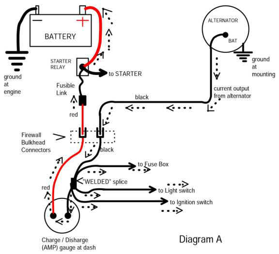
Look over this diagram at MAD. It is a simplified overview of how most of these cars get "main power"

http://www.madelectrical.com/electricaltech/amp-gauges.shtml

Follow along. Start at the starter relay. Power comes from the starter relay "big stud," through the fuse link, through the bulkhead, (the red wire) and to the ammeter

Through the ammeter, we are now in the under--dash harness in the black ammeter wire. The wire goes a few inches, and gets to the factory "welded splice". This is taped up in the harness under the dash. From that splice, a BIG RED wire takes off and goes to ..............the ignition switch. In the MAD diagram below, that is the bottom right hand wire coming off the splice

amp-ga18.jpg


Now, follow the diagrams from the 71 shop manual

In the top drawing.........the ammeter, we have a black and a red wire. The red wire is power coming IN from the bulkhead as in the MAD diagram, through the ammeter, and out on the BLACK wire.

Second diagram, is the under-dash welded splice. Notice in the ammeter diagram that the black wire on the ammeter is wire no R6A-12BK. This means a no 12 BLACK wire. R6A is an arbitrary circuit number.

Now look at the welded splice. Notice that there is a wire no R6A-12BK coming in from the middle right. That is the wire from the ammeter.

Now go to the ignition switch, 5th wire from the top. Notice at the left that it says J1-12R battery. Now look back at the splice. Top left wire is J1-12R. So that is power going OUT of the splice TO the ignition switch.
 

Attachments

  • 71ammeter.jpg
    5.6 KB · Views: 466
  • 71SPLICE.jpg
    9.5 KB · Views: 498
  • 71IGNswitch.jpg
    38.1 KB · Views: 574
Damn you are good! LOL. I was looking at that and the damn manual didnt state what that 1 with a diamond around it was.... I had no idea and it didnt make any sense. Now that it was explained to me it does.

So Im still stumped then. I've heard of the amp meter bypass which I would do when I rewire the car. That wire from the battery would still have to go to the ignition switch. Which is carrying a large load right? So is that the wire I would connect to the relay at #30 and the other side of it go to #87? Or am I thinking of this all wrong?
 
No, if you are just referring to operating only the ignition circuits by relay, you would want the dark blue "IGN1" wire

This (dark blue) is the OUTPUT of the switch going out through the bulkhead to the loads under the hood.

Read through that MAD article carefully. If you can, print it out. The whole deal with "the bypass" is that it's a sort of trick. The old red wire and the old black wires coming through the bulkhead end up (after the mod) as acting as ONE BIG wire. This mod does at least three things........


1......Using both the red and black wire as power feeding into the interior, means you essentially are now using a larger wire into the interior

2......At the same time, you are ELIMINATING the charging (alternator) current coming in/ out of the interior, because the alternator is now feeding the battery directly

3....You are eliminating the two largest problems with the bulkhead connector........that is, eliminating the actual connector terminals going through the bulkhead, as they are feeding the wires "straight through"

Bear in mind this mod does not relieve any load on any of the switches. It DOES relieve the load on the "main power" coming into the car, and if the ammeter is "shakey" solves that problem by bypassing it.
 
So let's say you want to run all your "dark blue" 'igniiton run' loads on a relay. You would CUT the "dark blue" which comes OUT of the bulkhead and feeds TO the regulator, and ignition system

You would hook the blue end you cut.........coming from the switch.......and out the bulkhead........to terminal 86. You would ground 85. Now, when you switch on the key, the magnet will come on.

So how to switch the old circuit?

Well, you need POWER. So run a heavy wire, say, no 12, over from the starter relay stud (battery) through a fuse, and to terminal 30.

Hook your other "cut" dark blue ............the end which feeds power TO the regulator, ignition, etc, hook that wire up to terminal 87.

So you turn on the key, the magnet moves, and 30 and 87 become connected.

30 receives power from the starter relay stud, through the fuse, through terminal 30, through the contacts, out 87, and back out to the regulator and ignition system.

If I follow you correctly this is exactly how it would be wired and you are talking on the engine bay side correct?

View attachment StarterRelay-1.jpg

I wanted to make a relay panel under the dash. Everything could be moved to the inside of the car? Would this pose any problems?

Ok, took some time and read and reread that MAD article. I now see how that battery wire at the column connection burnt up and you are now eliminating that problem by doing this.

Not sure if this matters but I will be gutting the factory wiring and replacing with a EZWire harness. Will anything else need to change since there are more dedicated circuits? I would still install the relays like we have been talking.

With that being said, the only thing I think you would need relays on are the following. Headlights, Fan, Fuel Pump, Ignition. You would not install a relay on the charging system correct?
 
SLS,
If I may jump in here, being as I have a little experience with electrical overcomplication.
The main reason you run a "control" circuit is to save money and weight. you can trigger a relay with 22ga wire for circuit that needs to run a very heavy gauge and amp load say 10ga/50amp. Now whether the control circuit draws its power from the circuit being controlled or a separate one is just a design choice. There are also circuits that are hot at all times and seeking a ground (ie. your courtesy lights).

If you go with a modern power distribution panel there will be all of these circuits already set up within the panel.

The rating on a multi-pin connector denotes per pin based on conductor size. There will also be a wire size range listed for the connector. Whatever the largest size is will be the limit of the pin in conductivity.

If you get a junkyard PDC cut the longest pigtails giving you the most wire to work with, it will really help.

Developing "Electrical" skills comes down to three things: learning how to solder, learning how to crimp on the brass part of the connector, and the most important keeping good records. If you know how to use Excel make a separate spreadsheet for each connector and keep it updated as you make changes. In my case I would bve lost in a minute without the documentation.

As far as connector choice goes weather-pac connectors are waterproof and great for the exterior. Molex connectors have a far greater density possible and are my choice for all the interior connectors.
first pic is the PDC from a 05 highway patrol crown-vic. 40 circuits lots of relays and control already set up, at the start of the process and the second is the documentation and the third is the finished piece.
I hope this helps and inspires, take your time you can do it
Andrew
 

Attachments

  • Photo393.jpg
    88.2 KB · Views: 497
  • Photo573.jpg
    86 KB · Views: 505
  • Photo568.jpg
    90.2 KB · Views: 498
  • Photo394.jpg
    101.6 KB · Views: 515
only thing I think you would need relays on are the following. Headlights, Fan, Fuel Pump, Ignition. You would not install a relay on the charging system correct?

I run the same relay on the regulator / field circuit as I do the ignition. Originally, on earlier cars (67-69) the only thing the dark blue ignition fed as it came out of the bulkhead was...........

ignition system (points)

and the regulator. End of story

In 70, 71, later, things got more and more complicated

The IGN1 fed the above, but ALSO fed

the blue alternator field on 70 / later alternator

idle solenoid on stuff like six pack cars

distributor retard solenoid some models.

electric choke if equipped

some models some smog doo dad.

So there was more and more LOAD on that IGN circuit

I'm always cryin' on here about "harness voltage drop." The more LOAD you put on a circuit, the smaller the WIRE SIZE is, and the more resistance you have in CONNECTORS and SWITCHES, then the more end - to - end voltage drop you have

Especially for the regulator, this is bad, because this causes OVER charging (over voltage)

I would run every under hood load that is switched off a relay. They don't all have to be divided. If you use a LARGE enough relay.......biggest example would be what's called a continuous duty solenoid........you could run any switched load under there including fans and still have plenty of switching capacity left over. I actually used to use one (overkill) on my old beat up Landcruiser. EVERYTHING that went through the ign switch was switched by that big solenoid.

The point is if you have large enough relays you can run multiple loads, just like everything had been hooked to the switch. Just don't overload the relay, or you'll be "in the same boat" you started with.
 
The main reason you run a "control" circuit is to save money and weight.

In a nutshell, that's correct, except in this case we are trying to also work around a "factory appearance" with the panel, and keep original switches, etc.

What he's saying is "you need larger heavier duty switches" And you need "larger heavier duty wire."

That is, headlights......you need a great big heavy switch, and great big heavy wire run all the way in from the battery, to the switch, to the larger dimmer switch, and all the way back out to the headlights. With modern, heavy headlights, you need larger wire, in addition to the wire being too light to begin with!!!!

Adding relays means you can come right off the battery with your short heavy wire, go through a relay, and you don't need much of a switch inside to control it.

By the way what is that fuse/ relay panel out of, is it easily re- configurable?
 
That photo you posted of the relay/ fuse box, what is it out of and is it easily reconfigured?

And I missed that you already said that.........

"PDC from a 05 highway patrol crown-vic"
 
The point is if you have large enough relays you can run multiple loads, just like everything had been hooked to the switch. Just don't overload the relay, or you'll be "in the same boat" you started with.

Do you happen to have a example of a relay that would be big enough?
 
It depends on what you mean by "re-configure" and what you mean by "easy".
Its just a box with fuses and relays already mounted, you cant change the internal busing, but its already set up for most things you will need and then some.
Andrew

"EASY"
 

Attachments

  • Inigo+Montoya+from+The+Princess+Bride+_5eb38f6e2f66bcfb3c178e52e0882339.jpg
    82.6 KB · Views: 524
It depends on what you mean by "re-configure" and what you mean by "easy".
Its just a box with fuses and relays already mounted, you cant change the internal busing, but its already set up for most things you will need and then some.
Andrew

"EASY"

HUH? I never said any of this is easy, Hence why Im asking all the questions. I understand how a relay works now. So now Im trying to figure out the proper way to install them in certain situations.

I get the headlights and smaller circuits. Im just trying to figure out the ignition side now.
 
You can get new pins for the steering column connector housing at radio shack. That's what I did and it's worked excellent.

I used weatherpacks everywhere else. I have the MSD crimping tool with the right dies for weatherpack and the original packard terminals
 
No in this image and in my electrical catalog they sell Bosch and Hella relays that have built in resistors between the two terminals I mentioned above. So Im wondering what the point of that resistor is?

View attachment 1714684804

That may be a diode, and BRINGS UP an important point

Depending on the brand, etc, some relays have a diode across the magnet (coil) terminals. This is intended to dampen spikes that might feed back into the switch/ controls

You want to use an ohmeter and determine if this is the case, as the diode will determine which terminal is negative (ground)

Here's a diagram depicting a built in diode:

Now conventional current (electron) flow through a diode goes from neg to positive AGAINST the direction of the diode "arrow" diagram, so neg to positive in this diagram flows from 86 to 85. YOU DO NOT want this, because that would make the diode SHORT around the coil. Smoke. Fire. Burned up diode. etc. Call the EPA

This means with this type relay, you would want to GROUND pin 85 and feed positive power to 86. This will cause the diode to turn off, what is known as "reverse biased." The diode will simply "sit there" and do nothing.

When you shut off the control voltage, the relay coil generates a SPIKE (pulse) of voltage just like the primary of your ignition coil. This spike will reverse polarity, turn on the diode, and for an instant, the diode will short out this spike or "dampen" the spike.

boschrelayschematicfromdatasheet01.gif
 
Well I will try to find just a regular relay. I wish I had your knowledge of electrical. Im much better now, but I used to be a pro at letting all the smoke out of things. Its amazing how much smoke they can pack into some things
 
Hey SLS, Im sorry I did not mean to put you down. In truth it is easy, but with that being said, its tedious, and under most circumstances a pain in the butt. It really is very basic. Just take one step at a time and you can do it. get a collection of reference material and dig in.The books suggested here are a good start.
Andrew
 
If you plan a lot of underhood relays, best to get a relay/fuse box from a latter car. I put one in my 65 Dart and 64 Valiant, as did 67Dart273. I used one from a 90's Jeep in both. Late 90's cars started to use plugs into the relay box instead of individual wires, so avoid those. I replaced most of my degraded engine wires with a 20 awg ribbon cable from the bulkhead connector.

A lot of work, but then your are ready for latter additions like electric fuel pump, EFI, ... I used the new relays to replace my factory starter and horn relays, so my firewall is cleaner and simpler. See my post on "modernized engine wiring" for more info (and look at my avatar). You will need to take over a big table for a few weeks, but a nice winter project while you watch TV.
 
Hey SLS, Im sorry I did not mean to put you down. In truth it is easy, but with that being said, its tedious, and under most circumstances a pain in the butt. It really is very basic. Just take one step at a time and you can do it. get a collection of reference material and dig in.The books suggested here are a good start.
Andrew

No offense taken! Thank you for your input to this thread, every little bit helps.

If you plan a lot of underhood relays, best to get a relay/fuse box from a latter car. I put one in my 65 Dart and 64 Valiant, as did 67Dart273. I used one from a 90's Jeep in both. Late 90's cars started to use plugs into the relay box instead of individual wires, so avoid those. I replaced most of my degraded engine wires with a 20 awg ribbon cable from the bulkhead connector.

A lot of work, but then your are ready for latter additions like electric fuel pump, EFI, ... I used the new relays to replace my factory starter and horn relays, so my firewall is cleaner and simpler. See my post on "modernized engine wiring" for more info (and look at my avatar). You will need to take over a big table for a few weeks, but a nice winter project while you watch TV.

Bill, Thank you also for the input into this. That was kind of my plan, it was going to be this winter, but not enough time. I want to get started on it earlier so I dont feel rushed to get it done by the time the weather is nice. Perhaps next winter, but its good to ask questions now and gather supplies so I have a head start on it.
 
straighlinespeed,
I expect in MN you will be socked in by snow drifts for another 4 months. We could use some of that precipitation here in CA. Folsom Lake is at a record low level. It was 65 F and blue skies again today, which is starting to really suck.
 
-
Back
Top