MS3 Pro Sequential Injection + Coil near plug conversion thread

-

goldduster318

Overzealous Car Modifier
Joined
Aug 25, 2007
Messages
1,971
Reaction score
675
Location
Lake Orion, MI
I'll be using this thread to document the conversion of my 1970 Plymouth Duster with highly modified 340 engine (dyno'd at 470hp and 455 lb-ft) to Sequential Fuel injection+ Coil near plug using a Megasquirt 3 Pro controller.

The parts are as follows:
Megasquirt 3 Pro computer
Aeromotive Phantom 340 Fuel pump system
Edelbrock Super Victor EFI intake
Holley 1000 cfm 4150 flange throttle body
1992-2003 Magnum V8 distributor for cam sensor
36-1 crank target wheel
3.0 V6 Ranger MY04 Crank Sensor
36 lb/hr injectors (Bosch)
Aeroquip PTFE braided steel line & Fittings
New Spectra CR11C gas tank
LSX "Truck" Round coils+ harnesses
Ebay fabbed polished valve covers

Follow along as I show what I have to do to install this system and also fix some rust on the trunk floor.
 
Part 1: Truck floor fix. The trunk floor had some rust holes in it so since the tank had to be removed anyway, I decided I would fix it with a new reproduction center piece.


Part 2: Modifying the new gas tank and trunk floor for the Aeromotive Phantom System. With this system in an A-body, you basically have three choices, move the tank down about 1" which would be difficult, add a relief in the top of the tank to mount the pump, or cut a hole in the floor and space it up at least 3/4"

I took option 3 to cut the trunk floor out. This car isn't stock and now I will have a hatch to work on the fuel pump if I need to in the future.


Part 3: the fuel supply system on the chassis side.

Aeromotive recommended using 3/8 feed and return lines for this setup, so I purchased a reproduction fuel line in 3/8 standard steel (right-stuff detailing), and a roll of 3/8 line, some holding clamps, and also used the -6AN Aeroquip PTFE line. I have a Parker rotoflare 37 degree flairing tool which works great on the steel line.


I added a fuel filter, which is basically the same fuel filter as my 2004 Chevrolet Colorado with some push fitting to AN adapters. I bought the whole kit from summit, can't remember the company at this point though. I installed it under the passenger seat and made a short section of line to re-connect since the bend wasn't quite right for it to connect on both ends with the stock line.


I mounted the fuel regulator completely to the passenger side of the engine bay. Shown here is the return line connected to the bottom. My setup will only have one return coming directly from the rails.

 
Looks like a good start. Did a MSII on a Slant Six a while back, I underestimated the exterior work with the pump, regulator, and injectors.
 
Nice work!

FYI, if you ever go to an NHRA track to run your car, your regulator mounted on the firewall will not pass tech.

Mike
 
Nice work!

FYI, if you ever go to an NHRA track to run your car, your regulator mounted on the firewall will not pass tech.

Mike

Interesting. I didn't know that. I'm guessing that's something about worrying if the flywheel will explode and cut through it or knock off the hoses. Seems a little ridiculous when there are two lines much closer to this that would be legal. I have an SFI bellhousing too.

At this point I am not worried about it. Once you see the engine bay with everything installed, you'll see that it's probably going to be difficult to have it 6" forward of the firewall without changing which end is the feed and which is the return, which would be an epic pain right now.
 
Part 4: Intake/Valve cover swap.

I needed to get the engine set up the way it was going to be before I started any wiring.

Before:


Taking it apart:


Going back together. This was pretty tough. Apparently this intake isn't really made to have the bolts installed nearest to the #3 and #6 intake ports. I was able to just cut down one of the bolts a bit for the #3, but I had to make a "really custom" bolt and a "really custom" allen key for the #6 one. All is good now. The valve covers (Ebay specials) had a really tough time fitting with the intake since there's even more to grind off due to the injector bosses. The valve covers have standoffs installed on them to hold the LSX round coils.


I can't get the hood all the way down yet, but it looks like it will clear. It seemed okay when I measured before I started installing...and I have seen other members use this intake before, but a different throttle body. The Holley 1000 cfm is a nice piece. It has a lot of the sensors installed already. You can see the wire hole on the firewall to the right of the heater core.
 
My hope is you'll provide some good detailed documentation on the MSD hookup, wiring, etc. Mopars and EFI info is lacking in many cases
 
Awesome transformation. WAY better than a carb style EFI setup.

Thanks. It should be better than that, there's so much capability to tune, I am not sure I will be able to take advantage of all of it. It's amazing when you look at this intake and it would be a 3000-8500 rpm range manifold with a carb and it should work fine here as it's really just dry flow now.

My hope is you'll provide some good detailed documentation on the MSD hookup, wiring, etc. Mopars and EFI info is lacking in many cases

The detail part might be hard to show. Honestly the wiring for this is almost identical to installing this computer on an LSX engine for most of the connections, which the MS3 Pro website has great detail on. You have to remember that that engine has a 4/7 swap in the firing order. You also won't have a MAF or knock sensors. The finer points like the magnum distributor and the ford VR crank sensor I am using aren't too bad either. I can try to cover those as best I can. I will show the crank target and sensor bracket once I am sure they work. Not 100% sure at this point.

The intake, fuel rails, throttle body, fuel pump module, and regulator are straight out of a catalog, so nothing real big going on there.

The sensors on the holley throttle body are the basic 80's-early 90's GM ones, except the IAC stepper motor is wired Dodge style. I will be using the mid 90's 1-bar MAP sensor and also the coolant temperature sensor. Both are spec'd for a 1994 Oldsmobile Cutlass Supreme 3.1L. That's also a great source for all the connectors, you can either get them at the salvage yards or order them through rock auto. I actually bought an NOS engine wiring harness for a V6 GM for the connectors.

There are really only a few wires that need to be connected into the car. In my case, this is a bit different since my car already has an aftermarket harness. I also have a delco 12SI alternator which is probably different from most people's stuff too.

The computer is now mounted right above the fresh air box door on the passenger side.


With it there, I used 2 screws plus some HD velcro. Should be fine with that. The ECU is light. The glovebox should also fit no problem even with the wiring in place and you won't notice it once installed.
 
Thanks. It should be better than that, there's so much capability to tune, I am not sure I will be able to take advantage of all of it. It's amazing when you look at this intake and it would be a 3000-8500 rpm range manifold with a carb and it should work fine here as it's really just dry flow now.


The detail part might be hard to show. Honestly the wiring for this is almost identical to installing this computer on an LSX engine for most of the connections, which the MS3 Pro website has great detail on. You have to remember that that engine has a 4/7 swap in the firing order. You also won't have a MAF or knock sensors. The finer points like the magnum distributor and the ford VR crank sensor I am using aren't too bad either. I can try to cover those as best I can. I will show the crank target and sensor bracket once I am sure they work. Not 100% sure at this point.

The intake, fuel rails, throttle body, fuel pump module, and regulator are straight out of a catalog, so nothing real big going on there.

The sensors on the holley throttle body are the basic 80's-early 90's GM ones, except the IAC stepper motor is wired Dodge style. I will be using the mid 90's 1-bar MAP sensor and also the coolant temperature sensor. Both are spec'd for a 1994 Oldsmobile Cutlass Supreme 3.1L. That's also a great source for all the connectors, you can either get them at the salvage yards or order them through rock auto. I actually bought an NOS engine wiring harness for a V6 GM for the connectors.

There are really only a few wires that need to be connected into the car. In my case, this is a bit different since my car already has an aftermarket harness. I also have a delco 12SI alternator which is probably different from most people's stuff too.

The computer is now mounted right above the fresh air box door on the passenger side.


With it there, I used 2 screws plus some HD velcro. Should be fine with that. The ECU is light. The glovebox should also fit no problem even with the wiring in place and you won't notice it once installed.

I love this thread already. Any chance you could detail how you did the trigger wheel for the ignition??
 
I love this thread already. Any chance you could detail how you did the trigger wheel for the ignition??

Well, at this point I'm not 100% confident that I installed it completely correctly as there's some some wobble to the tone wheel, but anyway, I bought a pre-cut tone wheel from a website called Miller's Mule, I believe it was 7" diameter. This welds to the crank pulley.

I then made the bracket for the crank sensor using some 3/4" square tubing to connect to the pan rail. You can do radial adjustment with washers on the pan rail and axial adjustment on the sensor itself.

Initial Mockup:


I had to cut a relief for the oil pan lip which isn't shown here and the dual groove pulley is a little different so I had to use some more washers

Installed on the car


Also here's the status as of Today. Need to button up all the stuff in the back at the gas tank now and then it's on to wiring.


I also will comment that the whole heater hose/gauge sender hookup at the intake is a serious compromise. I'm not sure I had too many other options.
 
Well I was hard at work on this project all weekend.

I installed the gas tank friday night but found that the filler neck opening in the tank was made 1/2" further forward than it should be even though this is supposedly a spectra "premium" tank, it's not a china one. This makes the filler neck not fit quite right at the body, and the floor gasket doesn't seal around the neck itself. Since I cannot return since it's modded, I'll have to see what it will take to make it work.

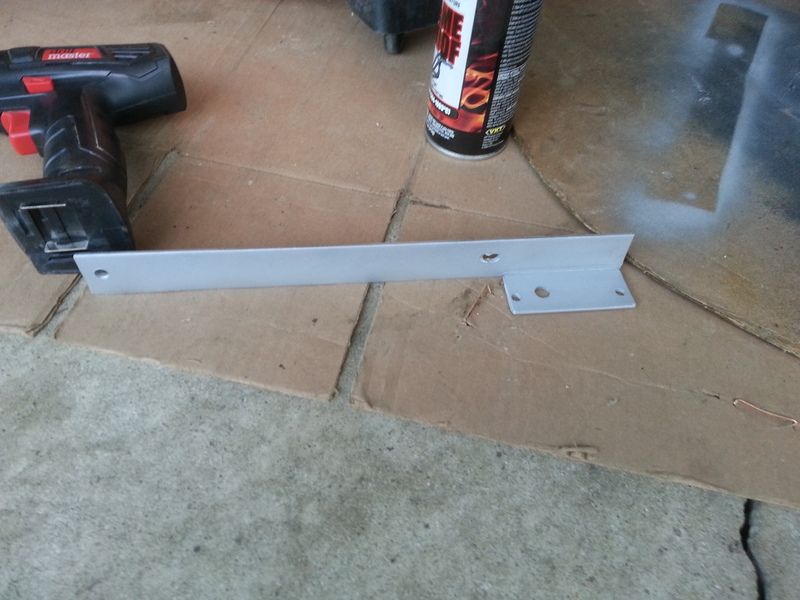
First thing I had to do before wiring was make a bracket for my GM style MAP sensor. This is the older style from the 1980s/1990s that's super common. I used the regular one bar since there's no forced induction here. Just some steel bar welded together. It mounts on the passenger side fuel rail between the rail and the intake runners. Almost invisible when installed!


I really got going on the wiring after that. It's pretty simple actually as the wiring harness that comes with the computer is marked on the wire. For the coils and injectors, they are "lettered" and you just arrange the letters in the firing order. Since we are 1-8-4-3-6-5-7-2, you just do A-H-D-C-F-E-G-B. The injectors need a 12V keyed power feed to the other side which you hook to the fuel relay (mine is fused separately with a 15A on the injectors and a 30 on the fuel pump with the Aeromotive Stealth 340 pump) . The coils need a 12V switched which I hooked to the standard ignition fuse that already existed in the car (I didn't have a ballast resistor, but if you did, you'd have to remove it and jumper them together), a ground (one on each bank if you used the factory 7 pin connector), a sensor return to the computer, and the control wires mentioned above). The wiring isn't too difficult, just tedious. You will need to be good at reading wiring diagrams, soldering and have some good crimping tools, heat shrink, and a good heat gun.

During:


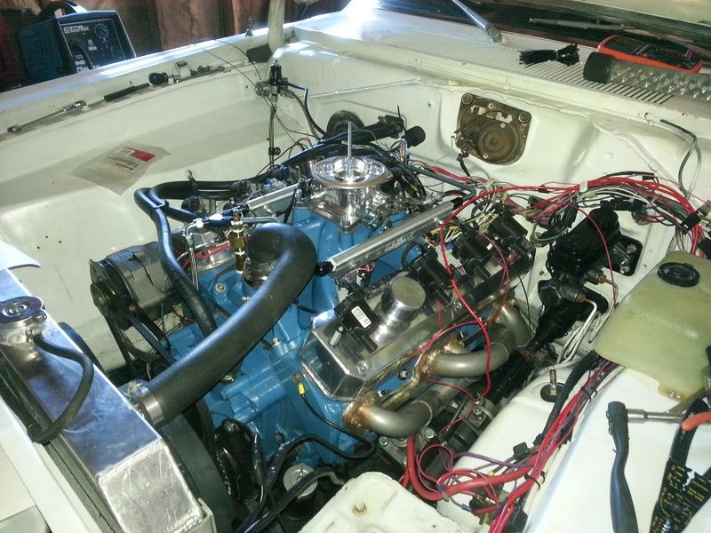
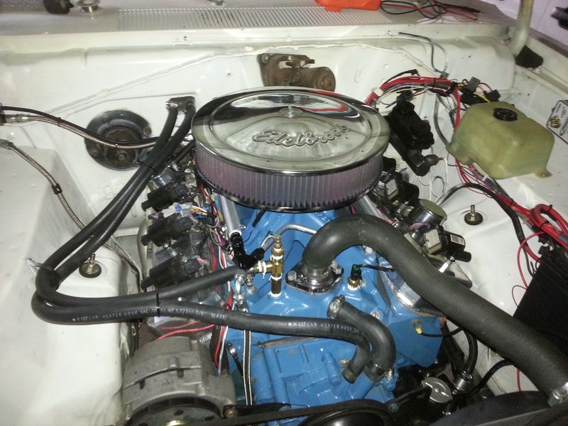
I managed to get all the wiring hooked up other than the VSS IN coming off my speedometer so I can get a speed in the computer/datalogs, and the fuel pump wiring itself. Here's it done, but not loomed (will do that eventually once I make sure I have all the bugs worked out)


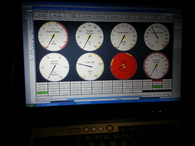
So with only that disconnected, I installed the ECU fuse and powered it up. I was able to connect to the ECU using my old Dell Latitude D830 Laptop (It has a serial port and USB but since that computer has a serial port I used it), and I programmed in my wideband (changed setting to get correct output), calibrated the tps, loaded the sensor calibration for the coolant temp, intake air temp, and MAP sensor, and was able to read all of those.


So, now, I need to get all the data for my crank and cam sync, finish the wiring, button a few things up in the car, and then get into all the test modes to make sure I wired it correctly and that I am getting signals correctly. If that's the case, I can flush out the fuel system, connect it, check for leaks, and then maybe give it a shot to see if she'll run.

I've probably worked on this thing for about 60 hours so far. Not going to be a super fast install if you're trying this at home. And that's AFTER I pre-built a few things.
 
One thing I noticed is your temp sender on that tee. That might not be a good idea. Let's say you get a slow coolant leak over night, like a weeping water pump. The coolant level might drop enough the gauge won't pick it up rapidly. You want the main gauge sender "where you'' can see it

(the GM "in the head" thing is a much better idea)

There are various places, makes spacers under the T stat housing, might be one approach.

If nothing else, interchange the EFI and the gauge senders

============================

Also "I wasn't thinking." Is the injector drivers different for the MSII and III? That is would you need the outboard driver module if you was to have used an MSII?

Typically when you get air pockets you get a "false high" reading with a jumpy needle, been through this with several cars where you have the engine temp sensor above the top of the radiator (my 1994 Cutlass Supreme 3.1L that I used to own comes to mind), and you had to bleed it out. Honestly it's not my favorite setup so I may consider one of those spacers if I can confirm that they actually work with a real thermostat.

At this point it's still lower than the inlets to the heater core and also the top of the radiator, so it "should" function. We'll see. I'll be driving around with the laptop open for a while. I think the CLT sender being accurate is actually more critical so long as you don't get a total trash reading on the gauge.

I am unsure about MSII. I never researched anything in depth other than the MS3X/MS3Pro. I think if you were considering MSII, you could probably just go with the Microsquirt instead, as I think they have similar functionality.
 
I was able to test all the coils, injectors, and the IAC using the built in test modes. All worked good. The spark sounded like a TIG welder.


Next I went to work on the cam and crank sensor. What they have you do is orient the distributor so the sensor pickup is basically right in the middle of the half-moon shape in the distributor. This is a different orientation than the stock 3.9/5.2/5.9 magnum orientation, but easy to achieve.

I then cranked the engine over and used the tooth logger in Tunerstudio:


Since it's a 36-1 wheel you want to see 34 normal teeth and one tall tooth, which is what you see here. The reason the tooth height is a little higher or lower is the speed changes a bit during cranking and I have a VR sensor on this engine. So this was good.

I switched over to the composite logger and looked for the cam sensor signal. No signal to be found. What it does is poll the cam wheel at the missing tooth to report the phase. After some testing I found that I was unable to get the +5V out when the metal "tooth" was inside of the switch (used a razor blade to test). So, it recommends installing a 1k ohm pull up resistor between the +5V feed from the computer and the signal wire. I had changed the connector to a weatherpack so I just soldered it on to the pins and fed the wire through the seal.


That fixed it, it switched immediately. The composite logger showed this:


The red pulses at the left are showing that it didn't see a cam signal yet. You can see it's showing the cam pulse in the green, meaning it polled the wheel and found a signal on every other crank revolution to know which stroke the engine is on.
 
Today I was able to shorten the spark plug wires and got the glovebox back in before it got dark. I just bought some taylor 8mm ends for the LSX coils and crimped them on to my original moroso 8mm wires. Kind of cool to not have to use wire separators or run them all over the engine.


Not too much left to go before I put fuel into it!!!
 
No, I put those in. I basically bought some #10 male-female standoffs, drilled holes in the covers, used nuts and lock washers on that side and tightened them up (the standoffs have a hex).

You can get some different coils that won't need at least as much of a standoff that come on some other LSX style engines. Wiring is the same. I got a deal on these "D585" round coils, and they are supposedly the best ones anyway.
 
I started today by completing the fuel pump wiring. The pump powered right up, I initially ran the output line into a bucket so that I could flush out any crap that was in the lines before it would get into the rails.

Once I had it all connected, I found that I had quite a few fuel leaks where my metal lines connected to the adapters/unions/tees. They basically just needed to be tightened up some more.

So then I let the spilled fuel dry and went to try to crank it up with pretty much the base programming on it...it started right up. Unfortunately it was running at 3000 rpm. I found that the throttle was a little open because the throttle cable was too tight. I corrected that and then it would run at 1500 rpm, but was very rich. I kept it running long enough to find that the fuel pressure was about 58 psi instead of 43.5 like it should be so I adjusted that down. It was still very rich, so I turned on the most amazing thing, the "Volumetric Efficiency Analyzer Live" (VEAL), which is basically auto tune. Within about 10 seconds it was running at a reasonable AFR and sounded a lot happier.

I ended up taking some timing out and turning on the closed loop idle control to get it to idle down correctly. VEAL seemed to help a lot there. When I checked the timing with my timing light it looked right on verses what the computer was asking for.

I got the car to warm up and I found that it re-starts pretty good, and I had very few issues. I have been going through all the settings and found that I had the wrong O2 settings which probably explains some of my issues.

Honestly there's very little to be afraid of here. The manual is very good for reference and it responds quickly. The VEAL is amazing.

Right now the car idles easily at 980 or so RPM with a 227/231 @.050 hyd. roller cam on a 110 LSA. It's never run this smooth. I wish it wasn't raining so I could work on it some more.
 
-
Back
Top