Need help with 383. Wont start.

-

kevin001

Member
Joined
Aug 24, 2025
Messages
18
Reaction score
2
Location
Oklahoma
So I bought a dodge wayfarer with I believe a 383. It caught on fire on the way home . Steps u have taken over to a two pin
.
Rebuilt carb.
Old coli 803, was melted on the front and had bubbled. Not good bought an elbrok coil installed.
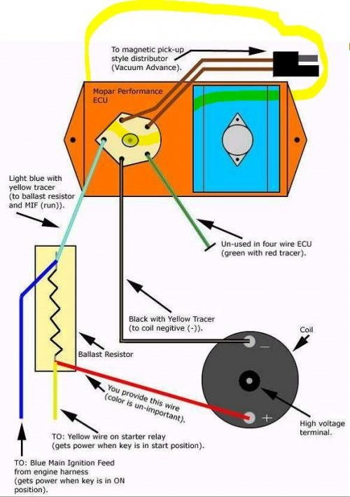
Bought a new distributor with I new 4 pin ECU installed 2 pin ballast
The alternator for some reason is wired into a sperate 2 pin ballast
I have foud that the brown wire is spliced Into the main blue wire. Where and what. should the brown wire be plugged into . Help would be greatly appreciated.
 
Pretty hard to help you from that post. I don't have access to service manuals for those. On the OEM A bodies, the brown bypass circuit, which is hot in start, should come out of the bulkhead and run to the coil side of the ballast. The "key" side of the ballast may branch off and feed the alternator field, for 70 and later, and regardless of year, feeds the IGN terminal of the voltage regulator.

You are saying the ignition coil is heat damaged? Maybe it was miswired and the ballast was not actually in the circuit. Pretty difficult to guess.

These colors may not match, so be careful. Also the yellow wire at the bottom of the ballast is WRONG. It does not go where shown, it would be the brown bypass wire

The top of the ballast is powered by the key in "run" and also is the electrical point to branch off for VR power (ign), alternator field, electric choke if used

wiring_6b409c1ef9a00fc2523cd6ad3131ce8bc68f2ef3.jpg
 
Speaking correct English in complete sentences and using correct punctuation will help you greatly here. Most people will fly on by if they have to try to translate poor grammar. Having said that, I'm not being the grammar police, but if you want help, you need to be much more clear.
 
First of all, welcome to the forum.
It sure would be polite if new members would introduce themselves before jumping in and asking for help. I've seen this happen on a few of the forums that I've been on and while there are polite members that may step in to help, I suspect that many others are turned off by what seems like a person taking without ever giving anything.
Secondly, yes....proper spelling and grammar are important. Nobody here is a rocket scientist or English professor but we aren't ignorant inbreds either.
Please remember to write in a manner that would make your teachers proud.
You will find that some members are eager to help if you are clearer with describing your situation. Pictures help too.
Good luck to you.
 
Last edited:
wiring_6b409c1ef9a00fc2523cd6ad3131ce8bc68f2ef3.jpg


The one thing missing from this is the case to the ECU need a chassis ground. So if it was replaced, verify its grounded and go over all the grounds as well.
 
The brown wire is 12 volts during crank only. It goes on the coil side of the ballast resistor. A log with the blue wire that goes to the + side of the coil.

The blue wire that has 12 volts with key on goes on the other side of the ballast.
 
First of all, welcome to the forum.
It sure would be polite if new members would introduce themselves before jumping in and asking for help. I've seen this happen on a few of the forums that I've been on and while there are polite members that may step in to help, I suspect that many others are turned off by what seems like a person taking without ever giving anything.
Secondly, yes....proper spelling and grammar are important. Nobody here is a rocket scientist or English professor but we aren't ignorant inbreds either.
Please remember to write in a manner that would make your teachers proud.
You will find that some members are eager to help is you are clearer with describing your situation. Pictures help too.
Good luck to you.
It certainly helps to get started off on the right foot. Well said.
 
First of all, welcome to the forum.
It sure would be polite if new members would introduce themselves before jumping in and asking for help. I've seen this happen on a few of the forums that I've been on and while there are polite members that may step in to help, I suspect that many others are turned off by what seems like a person taking without ever giving
First of all, welcome to the forum.
It sure would be polite if new members would introduce themselves before jumping in and asking for help. I've seen this happen on a few of the forums that I've been on and while there are polite members that may step in to help, I suspect that many others are turned off by what seems like a person taking without ever giving anything.
Secondly, yes....proper spelling and grammar are important. Nobody here is a rocket scientist or English professor but we aren't ignorant inbreds either.
Please remember to write in a manner that would make your teachers proud.
You will find that some members are eager to help if you are clearer with describing your situation. Pictures help too.
Good luck to you.

anything.
Secondly, yes....proper spelling and grammar are important. Nobody here is a rocket scientist or English professor but we aren't ignorant inbreds either.
Please remember to write in a manner that would make your teachers proud.
You will find that some members are eager to help if you are clearer with describing your situation. Pictures help too.
Good luck to yi

The brown wire is 12 volts during crank only. It goes on the coil side of the ballast resistor. A log with the blue wire that goes to the + side of the coil.

The blue wire that has 12 volts with key on goes on the other side of the ballast.
Yes. I understand this. The blue wire is ign on. The brown coil wire is cool positive and ign start
Gimme some! lol

IMG_20250915_133146510_HDR.jpg


IMG_20250915_133413271_HDR.jpg


IMG_20250915_133336653_HDR.jpg


IMG_20250915_133342008_HDR.jpg


IMG_20250915_133327413_HDR.jpg


IMG_20250915_133321912_HDR.jpg
 
Wiring makes my head hurt. Old fu**ed up wiring makes me barf. Obviously it ran before or did you buy the car not running? (No I didn't back read)
 

So I have the blue yellow wire spliced into the blue ign on wire and connected the the resistor. Then you can see I cut the brown wire which is spliced into the main wire. The brown wire is spliced into the purple wire which is connected to the positive side of coil the negative side of the coil black with a white stream is ran ton the ECU. The other two wires in the ECU are connected to the distributor.
Now someone has a second resistor connected to voltage regulator. The white wire with the black streamer then red wire that is spliced with white wire is the positive field generator the the third connection on the alternator is the green which runs back to the alternator. The black wire which is ground runs to the interior I believe
 
The brown wire is 12 volts during crank only. It goes on the coil side of the ballast resistor. A log with the blue wire that goes to the + side of the coil.

The blue wire that has 12 volts with key on goes on the other side of the ballast.
 
Pretty hard to help you from that post. I don't have access to service manuals for those. On the OEM A bodies, the brown bypass circuit, which is hot in start, should come out of the bulkhead and run to the coil side of the ballast. The "key" side of the ballast may branch off and feed the alternator field, for 70 and later, and regardless of year, feeds the IGN terminal of the voltage regulator.

You are saying the ignition coil is heat damaged? Maybe it was miswired and the ballast was not actually in the circuit. Pretty difficult to guess.

These colors may not match, so be careful. Also the yellow wire at the bottom of the ballast is WRONG. It does not go where shown, it would be the brown bypass wire

The top of the ballast is powered by the key in "run" and also is the electrical point to branch off for VR power (ign), alternator field, electric choke if used

wiring_6b409c1ef9a00fc2523cd6ad3131ce8bc68f2ef3.jpg
The new ICU is a 4 pin. Came with a two pin resistor . My understanding is that the brown is positive side. Of coil and engaged only when key is in start. The blue side is engaged when key is in the on position. The green red wire is no
 
Pretty hard to help you from that post. I don't have access to service manuals for those. On the OEM A bodies, the brown bypass circuit, which is hot in start, should come out of the bulkhead and run to the coil side of the ballast. The "key" side of the ballast may branch off and feed the alternator field, for 70 and later, and regardless of year, feeds the IGN terminal of the voltage regulator.

You are saying the ignition coil is heat damaged? Maybe it was miswired and the ballast was not actually in the circuit. Pretty difficult to guess.

These colors may not match, so be careful. Also the yellow wire at the bottom of the ballast is WRONG. It does not go where shown, it would be the brown bypass wire

The top of the ballast is powered by the key in "run" and also is the electrical point to branch off for VR power (ign), alternator field, electric choke if used

wiring_6b409c1ef9a00fc2523cd6ad3131ce8bc68f2ef3.jpg
 
So I have the blue yellow wire spliced into the blue ign on wire and connected the the resistor. Then you can see I cut the brown wire which is spliced into the main wire. The brown wire is spliced into the purple wire which is connected to the positive side of coil the negative side of the coil black with a white stream is ran ton the ECU. The other two wires in the ECU are connected to the distributor.
Now someone has a second resistor connected to voltage regulator. The white wire with the black streamer then red wire that is spliced with white wire is the positive field generator the the third connection on the alternator is the green which runs back to the alternator. The black wire which is ground runs to the interior I believe
Here's what that explanation reminds me of. Just messin with ya man. We're gonna try to help.

 
First thing I'd do is see what you have for power at the positive side of the coil. Both with the key on and also while cranking. Key on should be "somewhere" around 7-9V. While cranking should be closer to battery voltage. Check that and report back.
 
The resistor hooked to the VR is completely wrong, I can tell you that. Either of the field wires at the alternator connects directly into the blue "run" wire. The VR ign terminal, blue, also ties into the blue run. This only leaves one field terminal, normally green, that runs back to the VR. VR and ECU both MUST be grounded

The coil ballast is wired THE SAME for either breaker points or electronic

To add electronic to what is below, you simply hook the coil switch wire from the ECU to the coil NEG instead of the distributor, and add the ECU power lead, branched into the blue. Make no changes to the ballast/ coil wiring

"ignition 2" is the brown from the key as you say. Again, the blu "run" goes dead in start, the IGN2/ brown is the only power. The way it gets power to the ECU is, that the brown, during cranking, feeds the coil, BACKFEEDS through the coil ballast and to the box which should be branched in at the top of the ballast

As you say, you should not need the 4 pin ballast

Dual_Field_Alternator_Wiring.jpg


img[
 
Last edited:
If nothing else, jumper power temporarily to coil + make some tests. Be careful as this will eliminate the ballast in the circuit. Do not leave it connected longer than normal.

Crank either using the key or jumpering the start relay and test for spark at the coil lead
 
-
Back
Top Bottom