I'll take eggs. Scrambled with cheese.Wiring fire or did a spark catch fuel or fuel vapors? Or which came first, the chicken or the egg?
You are using an out of date browser. It may not display this or other websites correctly.
You should upgrade or use an alternative browser.
You should upgrade or use an alternative browser.
Need help with 383. Wont start.
- Thread starter kevin001
- Start date
-
Comin' right up. Hash browns too?I'll take eggs. Scrambled with cheese.
Dang right. lolComin' right up. Hash browns too?
mopar head
DoD nuisance Alien/Squatch extermination team
If I were you I buy/build a new ignition harness and start from scratch.So I bought a dodge wayfarer with I believe a 383
Copy the schematics provided and that should get you to big block Wayfarer bliss.
Welcome to the forum from a fellow big block Wayfarer owner.
What year do you have? and we need pics! lol
He doesn't have to build anything, really. Here's what I'd do.
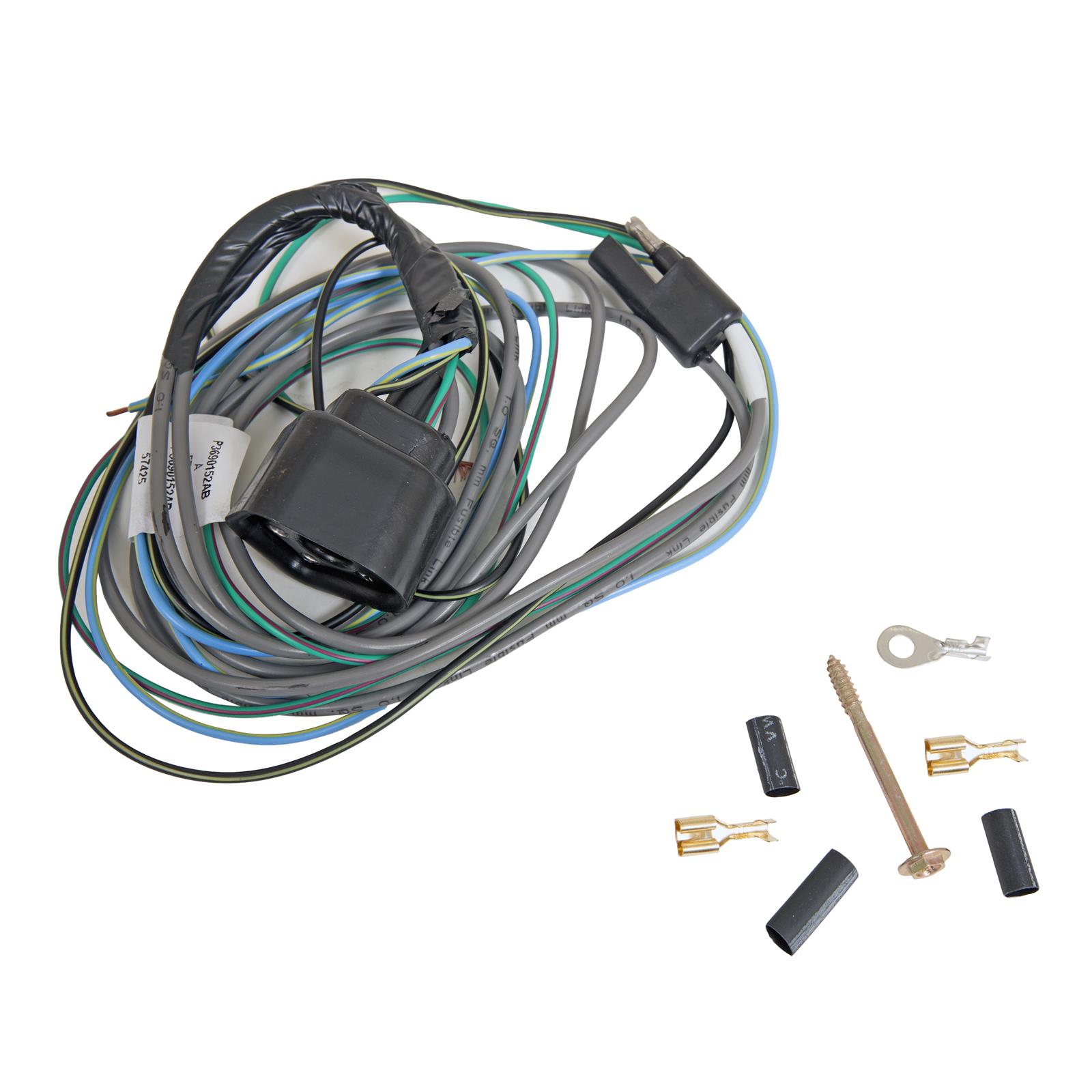
 www.summitracing.com
Summit Racing SUM-851010 Summit Racing™ Mopar Electronic Control Wiring Harnesses | Summit Racing
Free Shipping - Summit Racing™ Mopar Electronic Control Wiring Harnesses with qualifying orders of $109. Shop Ignition Box Wiring Harnesses, Distributor at Summit Racing.
See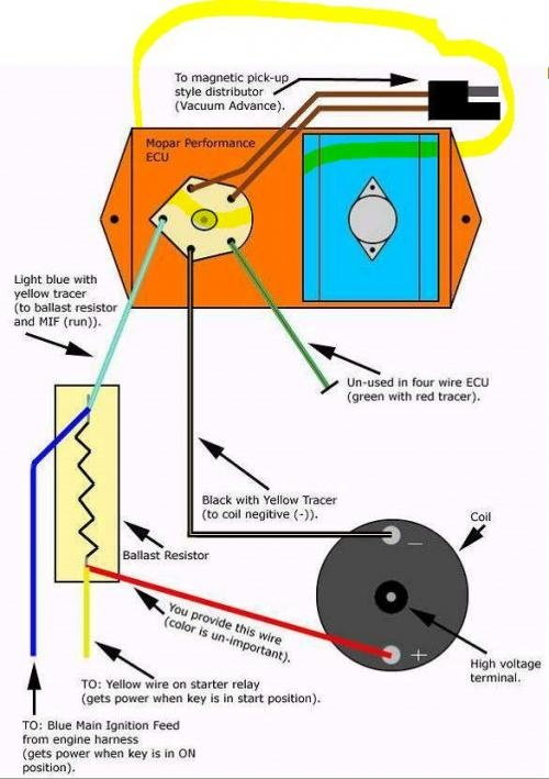
The one thing missing from this is the case to the ECU need a chassis ground. So if it was replaced, verify its grounded and go over all the grounds as well.where should I ground everything.. so the neutral ground to trans stopped working I grounded to the battery .
Here's what that explanation reminds me of. Just messin with ya man. Wow te're gonna try to help.
Lol. I am thinking that I may have a ground issue now. But I still don't know which coming off the steering column I need to connect to. Don't know the manufacturer of the column. I don't really know how to test it.
If I were you I buy/build a new ignition harness and start from scratch.
Copy the schematics provided and that should get you to big block Wayfarer bliss.
Welcome to the forum from a fellow big block Wayfarer owner.
What year do you have? and we need pics! lol
Mattax
Just the facts, ma'am
Well we know even less. This is not an A-body so even though we have some smarties, it will take extra luck for someone here to know exactly what you got from a few pictures. So best thing you could do is tell us what you bought and provide a lot of photos. Or maybe not a lot, just a lot that show what you have in terms of engine, wiring, and that will now include the ignition switch. And of course what year - cause some things changed every year - otehrs were the same and used across all car and truck lines.See
Lol. I am thinking that I may have a ground issue now. But I still don't know which coming off the steering column I need to connect to. Don't know the manufacturer of the column. I don't really know how to test it.
As far as grounds. Very little is grounded with wires. Engine to battery. Body to engine and/or battery. Headlights and sometimes some other lights.
- Joined
- Mar 6, 2008
- Messages
- 1,131
- Reaction score
- 803
Just to make sure: does the starter not turn, or does the starter turn but the engine won't take it from there?
mopar head
DoD nuisance Alien/Squatch extermination team
OK. lay off the schrooms and concentrate on wiring.I am painting my art in it
51 or 2 business coupe, mines a 52


I bought a 52 dodge wafere. Has a 76 383 with 727 trans.Well we know even less. This is not an A-body so even though we have some smarties, it will take extra luck for someone here to know exactly what you got from a few pictures. So best thing you could do is tell us what you bought and provide a lot of photos. Or maybe not a lot, just a lot that show what you have in terms of engine, wiring, and that will now include the ignition switch. And of course what year - cause some things changed every year - otehrs were the same and used across all car and truck lines.
- As far as grounds. Very little is grounded with wires. Engine to battery. Body to engine and/or battery. Headlights and sometimes some other lights.
The frame is a front and rear end are from a Chevy early 70s. Was the motor came in a coranet not if motor is a 383. Maybe 400. The original distributor part is 45 5, the 13875101 is for a 400. The first set of the numbers tell you the car I believe so the 45 5 should be a car. Not. The part says that I came out a family car
sure if a b or e body.
So it has 4 pin switch relay on it which is common.
Was going to a 5 pin ICU connected to a 4 pin ballast restistor connected with a green wire to the top set of pins where the 5 ohm resistance
Was. Replaced that with a four pin ICU the 4 pin moves the 5 ohm internally to the 4 pin ICU.
The plug for the 4 pin actually has a 5 pin harness.the green with red streamer is no longer used. Blue yellow is power the distributor pair and to the negative side of the coil. The purple wire coming off the positive side of coil goes to t the ign side of the restistor. Then ign start brown wire connects to steering column start.
Solid blue wire has a splice with the ICU power. Which is th ign on side .the coil is the other side.
Alternator three wires. Black. Ground and goes into the interior the amp appears not connected.
Green wire or field 2 goes to the voltage regular..
Red wire field 1 is spliced into the blue ign on wire with a splice to another 2 pin resistor which is connected to the top pin in the voltage regulator. Which is power.
Interior clock , amp radio present but not working or hooked up amp can cause some issues working gauges fuel and new tank.volatage temp gauges. .I will take some pics now that's from my memory. I can provide more details if needed. The headlights, wipers and turn signals work. All wire connections have orginal wiring cut to about 6 inches each . So I now can build a wiring harness from memory with colored wire. I do understand the system kind of.
Whew that's a lot 1So I bought a dodge wayfarer with I believe a 383. It caught on fire on the way home . Steps u have taken over to a two pin
.
Rebuilt carb.
Old coli 803, was melted on the front and had bubbled. Not good bought an elbrok coil installed.
Bought a new distributor with I new 4 pin ECU installed 2 pin ballast
The alternator for some reason is wired into a sperate 2 pin ballast
I have foud that the brown wire is spliced Into the main blue wire. Where and what. should the brown wire be plugged into . Help would be greatly appreciated.
So I bought a dodge wayfarer with I believe a 383. It caught on fire on the way home . Steps u have taken over to a two pin
.
Rebuilt carb.
Old coli 803, was melted on the front and had bubbled. Not good bought an elbrok coil installed.
Bought a new distributor with I new 4 pin ECU installed 2 pin ballast
The alternator for some reason is wired into a sperate 2 pin ballast
I have foud that the brown wire is spliced Into the main blue wire. Where and what. should the brown wire be plugged into . Help would be greatly appreciated.
The idiot had the positive coil feed wired directly into the ign on wireWiring fire or did a spark catch fuel or fuel vapors? Or which came first, the chicken or the egg?
Thanks for responding. I understand the how the system works. What I need to do now is to find the wire from the steering column to connect to the brown coil wire. The VR is hooked correctly but has the resistor in place. Which I will removeThe resistor hooked to the VR is completely wrong, I can tell you that. Either of the field wires at the alternator connects directly into the blue "run" wire. The VR ign terminal, blue, also ties into the blue run. This only leaves one field terminal, normally green, that runs back to the VR. VR and ECU both MUST be grounded
The coil ballast is wired THE SAME for either breaker points or electronic
To add electronic to what is below, you simply hook the coil switch wire from the ECU to the coil NEG instead of the distributor, and add the ECU power lead, branched into the blue. Make no changes to the ballast/ coil wiring
"ignition 2" is the brown from the key as you say. Again, the blu "run" goes dead in start, the IGN2/ brown is the only power. The way it gets power to the ECU is, that the brown, during cranking, feeds the coil, BACKFEEDS through the coil ballast and to the box which should be branched in at the top of the ballast
As you say, you should not need the 4 pin ballast


There may not be a column wire, if it's not a Chrysler column, or if it's a newer Chrysler.
Here's how this works
In the first 12V days, and up through Chrysler ECU breakerless in the 70's, Everything used a coil ballast. This was for two reasons. The ballast is what it says, a BALLAST. It helps sort of regulate the current through the coil. But it also allows for the 12V boost from the key direct to the coil during cranking, this gives you a hot spark for starting on cold days, or if it's flooded.
CHRYSLER WAS THE ONLY manufacturer to wire that up through the ignition switch.
"Everybody else", Ford/ GM had a separate small contact on the starter solenoid, both labled "IGN" for both Ford and GM That contact, on the solenoid, OUTPUTS 12V during cranking to directly feed the coil.
IF OUR COLUMN does not have such a wire there are some alternatives, no particular order:
1....You can put a 5A 50V or so diode in series with the "start" wire from the key and wire that to the coil +. The diode is to protect against backfeed. You can of course access that right at the start relay
2....You could add a small relay in parallel with the start relay, and use that to power the coil for cranking.
Do not try to use the "start" wire directly to feed the coil for bypass. When it is runnning, the "run" voltage to the coil will be loaded down by backfeed back to the start relay.
The photo of the VR, which actually is out of the problem until you get it running, looks like the wires were burnt. I would buy/ round up a VR pigtail and re work that. No idea why someone decided to wire a ballast resistor in there
-
Similar threads
- Replies
- 14
- Views
- 1K


