I'll keep it simple -I have a 1970 340 Duster, Entire wire harness in dash and engine bay has been replaced brand new. Car has been running fine for the past 2 weeks with no issues. Today I noticed that when I tried to start the car it would not fire up with the ignition to the start position. It will only start when I come off of the start position. When it does run my alternator gauge needle is indicating way to much overcharging. I also noticed that with my battery disconnected my alternator gauge needle is now not sitting on center. It is 1 indicator off center to the charge side. I'd appreciate any ideas or comments. Thanks in advance.
You are using an out of date browser. It may not display this or other websites correctly.
You should upgrade or use an alternative browser.
You should upgrade or use an alternative browser.
Overcharging Issue & Car Start Issue
- Thread starter bvfs12
- Start date
-
67Dart273
Well-Known Member
A Won't fire in start position
Have you changed the ignition, IE converted to Mopar ECU, MSD, other?
You must understand how Mopar ignition switches operate. There are several separate switches and circuits inside the "can" that we call the "ignition switch."
1 Dark blue, "ignition run" or IGN 1. Not fused, this is hot ONLY in run NOT in start, and feeds power to the ignition, the regulator "I" terminal, the alternator field, electric choke, if used, and maybe some smog doo dads. It also feeds power to the dash cluster and warning lamps.
THE ABOVE WIRE is NOT hot in "start."
2 Yellow, not fused, "start" goes from switch, through bulkhead connector to starter relay. If the clutch safety switch is engaged, or an automatic in park or neutral, this wire engages the starter relay and operates the starter
3 THE ONE you are having problems with, probably
Brown, not fused, hot ONLY in "start" goes only one place -- from switch, through bulkhead, to the coil + side of the ballast resistor. It is the only wire that supplies power to the ignition during cranking. You probably did not get it hooked up, or the bulkhead connector is not making contact
=====================================================================
B AMMETER. You may have a drain on the battery? To find out, with everything "normal," everything you know about shut off, including dome, courtesy lights, trunk light, etc, cigarette lighter, unhook the battery ground at the battery, and put a 12V test lamp in series with the cable neg. post to ground. IF the lamp lights, you have some sort of drain.
It MAY be that the (getting old) ammeter is just a bit sticky, and the needle decided to "land" there
=======================================================================
C OVERCHARGING. You may or may not have a problem. Make sure the battery is "up" (charged) very first basic test is to run the car at a good fast idle and check the battery running voltage right at the battery
Post back with that reading, we'll go from there
The brown wire is in the same terminal with the wire to positive side of the coil. So unless you pulled that wire terminal off the ballast resistor a portion of your starting current is going everywhere the blue wire takes it to. There isn't a diode there to prevent it.
This may not be a factor or any help, just saying.
This may not be a factor or any help, just saying.
With the car running I get 14.25V across the battery. Ohmed out ignition switch and all connections ohmed good. changed ballest resistor with no noted changes to problem. I have voltage to the (+) side of the coil during cranking but it still won't fire until I let off the the key from the start position. Checked the drain to ground with a test lamp in series with the (-) side of the battery. Anyway to check the regulator without replacing it? I just can't believe that my alternator is putting out way to much to overcharge the battery. As far as I know there's nothing in the alternator except windings. This car has been running the past 3 weeks with no issues noted !
67Dart273
Well-Known Member
14.25 is NOT overcharging
When you checked for voltage at the coil+ I want you to explain
HOW did you crank the car, IE use the key, or jumper the start relay?
WHAT exactly is "I have voltage" that is, how much?
When you checked for voltage at the coil+ I want you to explain
HOW did you crank the car, IE use the key, or jumper the start relay?
WHAT exactly is "I have voltage" that is, how much?
I checked the voltage to the (+) side of the coil by placing the red lead of my meter to the (+) side of coil and negative lead to the negative side of the battery. Voltage reads 11.5V when the key is in the accessories position and drops to 8.9V when we try to start the car. Car is being started by the key. Remember the regulator hasn't been replace yet. I realize the battery is low in voltage but the car will start even with the low voltage. My charging indicator on the dash reads pegged for charging at the higher RPM's. I think I might have damaged the indicator because with the car off and the battery disconnected it will not go completely back to center.
Not quite sure of what you mean by the statement "Those numbers are nearly opposite what you should see". As I stated in my previous post to your question of what the voltage drop was in start mode. The voltage drop was 8.9V. Voltage at the battery before start is 11.5V. With car running we have 14.25V across the battery.
The coil needs 12 volts in start and should get that from the ignition switch. In run the ballast resistor reduces coil voltage for no reason other than prevent the coil from over heating.
Do this, remove the coil wire so the engine cant start. Place volt meter on the battery. Hold the key in start position and see what the battery voltage drops to in 20 seconds. Below 10 volts , buy a battery.
Do this, remove the coil wire so the engine cant start. Place volt meter on the battery. Hold the key in start position and see what the battery voltage drops to in 20 seconds. Below 10 volts , buy a battery.
This still doesn't solve my overcharging issue. I'm cooking batteries here !
Bad battery, You have to understand that the engine/car can operate off the alternator. That alternater will run the car and cook a bad battery at the same time.
Doesn't mean the car will start or run on a bad battery though.
I would guess the sides of the battery are bowed outward. I would also guess if you pulled the blue wire off the alternater it never would start.
Just got back from the Auto Zone store and had them check the alternator and voltage regulator. The Alternator is putting out 14.5V and the voltage regulator checked out good with no problems. I can never know but I'm wondering if my battery had an internal short in one of the dry cells. I do have a another battery in the car now. Produces 14.3V across the terminals with the car running and the dash gauge reading overcharging. I still don't have warm fuzzies yet !!
67Dart273
Well-Known Member
Read this please!!!
And neither is this:
FIRST thing the VERY first thing I would do is "get a second meter." Your voltmeter may be AFU. If it is accurate, 14.3 is JUST fine!!!
I think your first battery is toast. Charge it up and have it LOAD TESTED
14.25 is not overcharging
And neither is this:
I do have a another battery in the car now. Produces 14.3V across the terminals with the car running and the dash gauge reading overcharging. I still don't have warm fuzzies yet !!
FIRST thing the VERY first thing I would do is "get a second meter." Your voltmeter may be AFU. If it is accurate, 14.3 is JUST fine!!!
I think your first battery is toast. Charge it up and have it LOAD TESTED
I did another test tonight. So far for what I know is this. The car will not start when the key is placed to the Ignition 2 position (Run). It only starts when the key is released from Ignition 2. Ignition switch ohms out good. When car is running at 1K RPM I get 13.3V across the battery. At 3K RPM I get 17.28 across the battery.
The alternator was tested good with 14.25V output and the regulator bench tested good on a diagnostic checker. All was installed back into car before these checks were performed.
The alternator was tested good with 14.25V output and the regulator bench tested good on a diagnostic checker. All was installed back into car before these checks were performed.
do you have a 4 post ballast? if so make sure it is hooked right. I had one that was mounted bottom side up and it would make it charge at 17-18 volts. I know someone will say you can only mount them one way but I know better.
67Dart273
Well-Known Member
SEVENTEEN VOLTS??? NOW we are talking overcharge
You need to make a couple of tests. You will be checking what is ACTUALLY coming through the bulkhead to the ignition and charging system
1: Turn the key to "run" with engine off. Hook your meter to the blue field wire of the alternator, and the other probe to the battery positive post. You should read very LITTLE voltage, the LOWER the better. More than .3V (three TENTHS of one volt) means you have a voltage drop in the harness between the battery, through the firewall, through the switch, and back out the firewall (on the dark blue IGN1/ "run" wire)
The circuit path involved is Battery -- fuse link -- bulkhead connector -- ammeter circuit -- ignition switch connector -- through the switch -- back OUT the switch connector (dark blue "run") back OUT the bulkhead connector, -- to the ign system, alternator field.
Your top suspects in the case of a high reading are:
Poor bulkhead connections, ignition switch connector, the switch itself, the ammeter, or the welded splice supplying power to the IGN switch.
2: Clip your meter to the coil POS terminal, and the other wire to battery POS terminal. Watching the meter, twist the key to START. Once again, you are hoping for a very low reading, the lower the better. Anything over .3--.4V (that is TENTHS of one volt, again) means you have a drop in the brown bypass IGN2 circuit.
This circuit path is similar:
Battery, -- fuse link -- through the bulkhead -- ignition switch connector -- through the switch -- back out the switch connector (on brown bypass, or IGN2) -- back through the bulkhead, -- to the coil + side of the ballast resistor
In this case your top suspects are again similar:
Bulkhead connector terminals, the IGN switch connector, the switch, or the ammeter or welded splice.
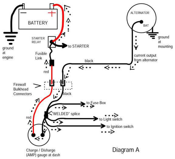
3: If you have not done so read the MAD article, which gives an overview of how this comes to be, and the simplified diagram down the page shows much of what I just mentioned:
The article:
http://www.madelectrical.com/electricaltech/amp-gauges.shtml
The simplified diagram.
Follow the path from the battery, fuse link, bulkhead, ammeter, etc. NOTE the "welded splice." These do not fail often buy they DO and CAN and HAVE. This is a factory splice in the under-dash harness, a few inches down from the black ammeter wire. NOTE that it supplies power TO the ignition switch
NOT shown in this diagram is the:
dark blue "run" going back OUT through the bulkhead (IGN1)
brown "bypass" going back out through the bulkhead (IGN2)
WHY IS THIS SO important? Because voltage drop in these two circuits will cause:
Poor starting which you have
Overcharging which NOW we see that you have. Every tenth of a volt DROP in the dark blue "run" wire will ADD one tenth to the CHARGING voltage.
4: LAST
Check the GROUND circuit of the voltage regulator.
With the engine running to simulate "medium cruise, hook your meter to battery NEG and to the voltage regulator mounting flange. You again should read nearly ZERO volts. If you read more than .2V, you have a ground problem between the regulator, the battery, body and block.
You need to make a couple of tests. You will be checking what is ACTUALLY coming through the bulkhead to the ignition and charging system
1: Turn the key to "run" with engine off. Hook your meter to the blue field wire of the alternator, and the other probe to the battery positive post. You should read very LITTLE voltage, the LOWER the better. More than .3V (three TENTHS of one volt) means you have a voltage drop in the harness between the battery, through the firewall, through the switch, and back out the firewall (on the dark blue IGN1/ "run" wire)
The circuit path involved is Battery -- fuse link -- bulkhead connector -- ammeter circuit -- ignition switch connector -- through the switch -- back OUT the switch connector (dark blue "run") back OUT the bulkhead connector, -- to the ign system, alternator field.
Your top suspects in the case of a high reading are:
Poor bulkhead connections, ignition switch connector, the switch itself, the ammeter, or the welded splice supplying power to the IGN switch.
2: Clip your meter to the coil POS terminal, and the other wire to battery POS terminal. Watching the meter, twist the key to START. Once again, you are hoping for a very low reading, the lower the better. Anything over .3--.4V (that is TENTHS of one volt, again) means you have a drop in the brown bypass IGN2 circuit.
This circuit path is similar:
Battery, -- fuse link -- through the bulkhead -- ignition switch connector -- through the switch -- back out the switch connector (on brown bypass, or IGN2) -- back through the bulkhead, -- to the coil + side of the ballast resistor
In this case your top suspects are again similar:
Bulkhead connector terminals, the IGN switch connector, the switch, or the ammeter or welded splice.
3: If you have not done so read the MAD article, which gives an overview of how this comes to be, and the simplified diagram down the page shows much of what I just mentioned:
The article:
http://www.madelectrical.com/electricaltech/amp-gauges.shtml
The simplified diagram.
Follow the path from the battery, fuse link, bulkhead, ammeter, etc. NOTE the "welded splice." These do not fail often buy they DO and CAN and HAVE. This is a factory splice in the under-dash harness, a few inches down from the black ammeter wire. NOTE that it supplies power TO the ignition switch
NOT shown in this diagram is the:
dark blue "run" going back OUT through the bulkhead (IGN1)
brown "bypass" going back out through the bulkhead (IGN2)
WHY IS THIS SO important? Because voltage drop in these two circuits will cause:
Poor starting which you have
Overcharging which NOW we see that you have. Every tenth of a volt DROP in the dark blue "run" wire will ADD one tenth to the CHARGING voltage.
4: LAST
Check the GROUND circuit of the voltage regulator.
With the engine running to simulate "medium cruise, hook your meter to battery NEG and to the voltage regulator mounting flange. You again should read nearly ZERO volts. If you read more than .2V, you have a ground problem between the regulator, the battery, body and block.
67Dart273
Well-Known Member
do you have a 4 post ballast? if so make sure it is hooked right. I had one that was mounted bottom side up and it would make it charge at 17-18 volts. I know someone will say you can only mount them one way but I know better.
A wrongly wired 4 terminal ballast WILL NOT cause overcharging
Bulldozer
free ice cream sandwiches
This still doesn't solve my overcharging issue. I'm cooking batteries here !
read through this thread PLEASE ...
http://www.forabodiesonly.com/mopar/showthread.php?t=173673
67Dart273
Well-Known Member
I'll tell you what. Give me a day or so to investigate and digest what you said here and I'll be back in touch with a post. Thanks for the information. Will look into this.
Most certainly. If you run into difficulty with these tests, post back.
At first, what you describe did not seem like overcharge, but evidently you didn't have the engine running fast enough at the time.
I made a couple of measurements as you suggested. Here are the results.
Turn the key to "run" with engine off. Hook your meter to the blue field wire of the alternator, and the other probe to the battery positive post. VOLTAGE MEASURED WAS .18V
Clip your meter to the coil POS terminal, and the other wire to battery POS terminal. VOLTAGE MEASURED WAS 9.6V
Turn the key to "run" with engine off. Hook your meter to the blue field wire of the alternator, and the other probe to the battery positive post. VOLTAGE MEASURED WAS .18V
Clip your meter to the coil POS terminal, and the other wire to battery POS terminal. VOLTAGE MEASURED WAS 9.6V
67Dart273
Well-Known Member
Your first test is OK
Confirm what you did on the second:
Should have meter on coil POS, and battery POS and measure the voltage
WHILE CRANKING and you MUST use the key to crank the engine
If that is what you did, you have problems in the brown bypass wire circuit
Either it's not hooked up
or bad connection through bulkhead
or bad connection at ignition switch connector
or that contact of the switch is bad.
You do not HAVE to replace the switch if that turns out to be the probem, there are "other ways."
IF the above is indeed how you ran the test, get access to the IGN switch connector and measure the brown wire, while cranking, using the key, between the switch connector and battery positive.
OK. This is where i'm at now. I just went ahead and replaced the regulator and the ballast resistor. It only seem to make sense as the regulator suppose to regulate. Auto Zone called the old one good with their bench testing of it but I put in a new one in the car anyways.
Results: I monitored the voltage with a volt meter while driving the car. At idle the voltage was around 12-12.5V. Driving it stayed between 13.0 to 14.25 with an occasional once or twice 15.5V. My charge indicator on the dash stayed at center and didn't move much but there was a time or two where the gauge pegged out and stayed at overcharge. I wasn't reading my volt meter while that was happening.
During while this was happening there were times where I would turn the car off and then try to start it and it wouldn't start. I've been reseating the ignition column connector to the main wire harness a few times. This is a brand new wire harness in the column and dash. I'm really wondering if I have pin problems and I'm compounding a lot of my problems.
The one issue that still plagues me is the car still will not start when turning the key to the start position. It will only start when the key is released from the start position.
67Dart273
Well-Known Member
Which is why I asked you the last question about your voltage test
The "occasional" pegging, and 15.5 is troubling. You have an INTERMITTENT somewhere.
I may have said earlier, but if not, you need to inspect the bulkhead connector carefull.
The "occasional" pegging, and 15.5 is troubling. You have an INTERMITTENT somewhere.
I may have said earlier, but if not, you need to inspect the bulkhead connector carefull.
-


