So,I decided to try this

-

1BadDodge71

FABO Rice Hater
Joined
Aug 17, 2006
Messages
2,067
Reaction score
1
Location
Fort Collins,Colorado
I came across this article on Allpar.com on swapping out the crappy voltage regulator on the dash cluster of my Duster for a Solid State TO-220 5v regulator and decided to try it out on a spare cluster I have.
http://www.allpar.com/history/mopar/electrical2.html
I will be putting it back together and see how it goes because last time I used this cluster even with a brand new fuel gauge sending unit and ground strap,the gauge was still acting up.
I will post the results later on.
 

Attachments

  • IMG_0180.jpg
    44.2 KB · Views: 256
  • IMG_0181.jpg
    30.6 KB · Views: 273
  • IMG_0182.jpg
    41.1 KB · Views: 273
I would seriously consider redoing what you have done there. For a few reasons

1...Hard to tell looks like a poor solder joint or two. maybe

2...It appears you soldered to the IVR socket terminals. Those have a bad habit of 'not' being in contact with the board traces. Consider scraping the board trace and soldering to that

3...The biggest concern I have, is the very large and very unsupported wire. That "may" rattle around with use, and it's own weight and inertia, and break loose and cause a short or other problem. Consider re-working with smaller wire. A good cheap source of wire is a scrap length of something like CAT-5 cable.

4...One way to support all that.......regardless of weight and size, is to glue it down with something like GOOP. Yes, that is a brand name, LOL. Any hardware store has it.

Also.......on a side note, I hope you installed a ground pigtail

Re-worked the cluster connector pins

and loosened / tightened the gauge stud nuts.
 
I did it years ago. With heat sink, works very well
 
I have to agree with 67Dart about the dangling wires. I used a small perf board and mounted the regulator, heat sink & cap to it. Then I ran 3 short wires to the appropriate places for a nice neat package. It's still working great after 5+ years. For what it's worth, you may want to add a heat sink to your design.
 
I went to the RTE website to see if your plan was a good one and here is what they say (http://rt-eng.com/rte/index.php/RTE_Limiter_Faq):

"The linear regulator will dissipate a lot of heat because it is constantly dropping a lot of voltage across it in order to create 5V all the time. In fact a linear regulator will generate a lot more heat then the original limiter. It is necessary to thermally bond the linear regulator to the limiter case to keep the regulator from getting too hot under normal operation. For reference, it takes about 300mA per gauge to make each gauge read full scale. Therefore the amount of heat generated by the linear regulator is P=IV=300mA*(12V-5V)*3=6.3Watts. This is a lot of heat.
The linear regulator requires a good ground just like the original limiter. If the ground is lost, then the linear regulator will put out +12V all the time, frying the gauges.
The linear regulator will not properly emulate the original limiter in the sense that the original limiter puts out +12V for 3-4 seconds at initial power up in order to get the gauges up to their correct reading quickly. It can take up to 1 minute for the gauges to reach their final reading when using a linear regulator after turning on the key.
The original mechanical limiter pulses on and off, and this has the effect of overcoming friction inside the FOT gauges. This makes the gauges more responsive to changes. Since the linear regulator doesn't pulse, it doesn't have this effect.
Rarely some linear regulators can fail when their output is shorted to ground. Usually when they fail, they will short the input to the output, causing +12V on the output of the regulator.
On a positive note, most linear regulators have heat sensors inside them and will shutdown when they get too hot (caused by the output being shorted to ground)."

So for $50 spent at RTE, you get a pre- engineered solid state replacement regulator that has a fuse and other safety features. This is the way i'll be going on my dash rebuild.
 
Also, you MAY be able to mount the VR over there on the GND of the PC board clean up the copper well and make sure it's flush mounted. The center GND wire is the same as the screw mounting tab.

My photoshop skills ain't good LOL
 

Attachments

  • gnd.jpg
    50.1 KB · Views: 225
Hey, try anything once! Sometimes two or three times.

I had the same issue with my fuel gauge in my 66 barracuda. I used the 7805 5v regulator. Yeah, I know, I used all red wire...it's what I had.

Once I got the voltage regulator working, my gauge would read 5/8 when full. Sending unit measured correct resistance out of the car.

I did it about a year and half ago, but just the other day I filled up and the gauge went to 7/8!

I should add that a couple of FABO members guided me through the repair: Pete_in_NH and nm9stheham. Thanks!


Here's a picture of my repair.
 

Attachments

  • IMG_20141106_190827.jpg
    37.9 KB · Views: 229
I followed the Allpar directions, works very well. Heat sink needed on yours I think.
 
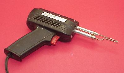
Yeah,my soldering looks messed up because my Weller soldering iron wasn't working well so I had to use my small soldering iron.
I do have a set of heat sinks on the way so for now It's mounted on a piece cut from a larger heat sink dabbed with heat grease I use for GM HEI modules.The guy at the electronic shop I bought the capacitor and regulator from said it would be fine to use the piece from a larger heat sink and grease until the heat sinks arrive.He was out of stock.I know it's crude looking ,but everything is tight.Like I said,it was a spare circuit board and I was experimenting.
 
Well,installed it and it started it and everything works fine.Nothing caught on fire,lol.
I'm very low on gas so I can't tell or not if its working better.I will have to fuel up so I can tell the difference.
 
my Weller soldering iron wasn't working well .

Is it a gun? I always "automatically" wiggle the nuts on the tip when I first fire it up, even after "only" a week of non use

gun1.jpg


I've got enough soldering equipment over the years, LMAO if I fired 'em all up at once I could heat the house
 
This is a big improvement over OEM. that setup was antiquated to say the least.:burnout:MT
 
This is a big improvement over OEM. that setup was antiquated to say the least.:burnout:MT

Well "most of em" did it LOL. Ford, I think AMC, and of course, Chrysler corp. I don't know who else. GM took a different approach.

First one I had went bad was the late fall of 67, I had a 60 Ford falcoon with the 85 hp 144 cid six, and a GLASS float bowl on the Holley 1bl.
 
Well "most of em" did it LOL. Ford, I think AMC, and of course, Chrysler corp. I don't know who else. GM took a different approach.

First one I had went bad was the late fall of 67, I had a 60 Ford falcoon with the 85 hp 144 cid six, and a GLASS float bowl on the Holley 1bl.
I remember the first time i tried to get a voltage reading off one of these, I'm like WTF? It wont stay in one place! then I figured out why and its "you have to be kidding!" AND of course the voltage reg works the same way! why do my light flicker! LOL
 
I remember the first time i tried to get a voltage reading off one of these, I'm like WTF? It wont stay in one place! then I figured out why and its "you have to be kidding!" AND of course the voltage reg works the same way! why do my light flicker! LOL


I thought the same thing! A set of points in the fuel gauge!!!!!! WTF!:wack:

I suppose for the time, it was "advanced"...
 
-
Back
Top