voltage problems

-

duster-z

Well-Known Member
Joined
Jan 26, 2011
Messages
45
Reaction score
2
Location
Kansas
ill try to keep this short
first off i have a 72 duster with a 360 v8 in it with electric ignition.
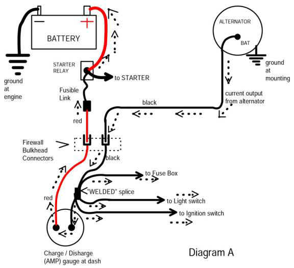
i have removed the amp meter since it almost caught my car on fire and i added the electric ignition my self and when i first got the car the voltage regulator went out and i replaced that also.

now for the problem when im driving my car the voltage meter reads between 13.8 to 14.9 and my turn signals work fine. then when i go to slow down and stop, the voltage slowly goes down and the turn signal starts to slow down, then when i get stopped and the car idles the voltage rests at around 10.8v and the turn signals freezes. when i feather the gas the voltage goes back up.

if it matters my idle is around 600 rpm

im assuming it has something to do with the alternator but i dont want to just start replacing parts and hope it fixes it.

any advise would be great.

Thanks.
 
That's normal for Mopars with factory electronics. I'd replace the voltage regulator with an aftermarket one. I use the Ron Francis regulator with the factory alternator. My voltmeter is about 14V steady at idle.
 
Uh, no, it is not "normal."

(NOTE I realize you said you bypassed the ammeter so this is somewhat general Read around that part)

You have a bad voltage drop, there, somewhere IT MIGHT ALSO BE that you have a damaged alternator, that is, a bad one or two diode pair.

Start by reading the MAD article:

http://www.madelectrical.com/electricaltech/amp-gauges.shtml

and do some testing to figure out WHERE you are losing voltage.

Start by checking right at the battery terminals, and then moving your meter to someplace "easier" to deal with like, the firewall for a ground, and the starter relay battery stud for a battery ground point. Let the engine idle slow. I bet it's NOT 10 v !!!!

Now turn on the lights, heater, etc. I bet it's STILL not 10 v!!!!

Find out WHERE you are losing the voltage.

Your top suspects in this deal are things like the terminals in the bulkhead / firewall connector, the ammeter terminals, the ammeter internal guts, the ignition switch connector, the switch itself, the fuse panel, and in rare cases, the "in harness splice which is a welded splice (refer to the MAD article) in the black ammeter wire.

If you need specific help keep posting to this thread.

The diagrams in the MAD article are good for a basic distribution, and you can download free service manuals here

http://www.forabodiesonly.com/mopar/showthread.php?p=1970088617

Also, MyMopar has wiring diagrams that are sometimes easier to follow, but are less complete


http://www.mymopar.com/index.php?pid=31

Two diagrams

http://www.mymopar.com/downloads/1972/72ValiantA.JPG

http://www.mymopar.com/downloads/1972/72ValiantB.JPG
 
A little slowdown of the signals at idle is pretty normal, as is a little dimming of the headlights, but 10 volts at idle isn't.
Del is right that there has to be a big loss somewhere.

Just follow the powerflow with your meter until you find a spot that it drops in voltage.
I'm betting on the bulkhead connector.
 
Aftermarket underdrive pulleys do the same thing. At only 600 rpm curb idle you might need a overdrive pulley.
 
Hey OP, where is the voltmeter located? In-dash cluster? Or on-dash? And where is it connected? If you tell us this, it will help us understand exactly what is being measured by your voltmeter.

Is this a new problem for this car that just developed, or has it been there all along?

How old is the battery?

Do you have a multimeter? You really need one for this and will use it over and over on cars in the future.

If you want to actually troubleshoot and better locate the problem, it would be very helpful to everyone to know the following information:
A. When the engine is cold, what is the voltage indicated on your in-car voltmeter when you turn the ignition to the run position but do not start? Also, what is the battery voltage when the engine has not been run overnight and you measure it with a multimeter?

B) With the engine warmed up and measured at both idle and at fast idle (around 1500 rpm):
1) Voltage with a multimeter at the alternator output (the large terminal on the back of the alternator) at both engine speeds
2) Voltage across the battery terminals at both engine speeds
 
What I meant by "normal" is the voltage drops at idle and goes up at rpm or speed.
 
ok so i went and took measurements with a very nice multi-meter and the digital voltage gauge is spot on,it is attached to the 12v feed to the instrument cluster. now for the voltages.
-to be clear at idle turn signals freeze completely

Battery: idle(with headlights)-11.8, high rpm-15.7, idle-12.54
Alternator: idle(with headlights)-12.26, high rpm-over 17, idle-13.37

at fuse block:

headlights on:idle- 11.2-10.8, high rpm- 13.8-14.6
Headlights & t/s: idle- 10.3-10.8
nothing on: idle- 12.0-12.5, high rpm- 14.6
Headlights & t/s & Brakes:idle- 10.0-10.6

now it does look like i have a voltage drop, but it also appears to me that i also have a problem with my alternator, from my knowledge in working at a mechanics shop the output from a alternator should be between 13.8 to 14.5( correct me if im wrong.)

in the future i will be completely rewiring the car which should take care of the voltage drop. i will also be installing sensitive electrical components e.g. custom led tail lights.

i have alot of knowledge in electrical stuff and have rewired a couple cars from scratch, but i am unfamiliar with the alternators in these cars which is why i posted this thread.

is there a way to make a stock alternator work properly in the standard voltage range. or would it be better to go with a different alternator set up?

sorry for the long post but thanks in advance
 
Where are you making the above measurements? I know you say "fuse block" But if you mean say, on the downstream side of some fuse, this could be because of a poor connection at some fuse

You cannot just probe around in there and make measurements. You have to think about what you are doing, and refer to a diagram, and see what it is that you are into

If you have not done so, go here and download the 73 factory shop manual:

http://www.forabodiesonly.com/mopar/showthread.php?p=1970088617


OK do not put too much stock in the actual output in the alternator output STUD, because what is happening is this

You have major circuits which CAN have voltage drop and which can cause drop and these are specific and separate circuits

1.......You have the GROUND circuit. Remember, the battery NEG, the block, the body are all separate, and must be grounded together. All components must be grounded to one of these, and rust, corrosion, size of wire, fastener looseness etc, can affect this. The voltage regulator MUST "in theory" be connected to the battery NEG post at a very low level This is not always so

2.....You have the alternator OUTPUT to the battery POSITIVE post and to the LOADS. This is actually the LEAST important, because the voltage regulator sensing circuit in some ways compensates for this. That is, the sensing circuit ramps up the alternator output if the battery voltage "goes low" until the battery voltage again comes up to the regulator "set point." This is why you got the 17V reading up above

3.......Last, you have one of the MOST important concepts, and this is the voltage drop in the "hot" section of the IGNITION harness. In a factory harness this is the entire circuit path from battery.......starter relay......fuse link.......bulkhead connector.......ammeter......ignition switch connections.....harness welded splice..........(branch off to the fuse panel).......through the switch...... back through the bulkhead......and to the regulator and other underhood loads........


ALL these sections work in concert against you to generate problems and voltage drops.

The "usual suspects" are ALWAYS

ground connections

bulkhead connectors

ignition switch connections

ignition switch

ammeter connections

ammeter internals

rare, but welded harness connections

fuse panel problems

other problems

un grounded or poorly grounded regulator

poor output alternator
 
Also, the MAD article gives a VERY nice "overview" and simplification of the power distribution:

http://www.madelectrical.com/electricaltech/amp-gauges.shtml

Follow along:

One thing this diagram does NOT show is the ignition switch and the path back to the regulator. But it DOES show the path through the bulkhead connector for the alternator, ammeter, and the "welded splice.

Let's say you are idling, with the headlights on, and you are showing 10V at your fuse panel. WHERE could you be losing this voltage? Look at the circuit? Measure as you go What is at the battery? What is at the starter relay stud? At the red wire going through the bulkhead?

You will have to be CAREFUL but can you get a clip lead up under the dash up to the ammeter? Would be wise to remove the battery ground to do so!!!! And measure voltage at the ammeter?

What does this gain you? This will show the battery voltage ON BOTH SIDES of the red wire connection of the bulkhead connector, that is, the connector coming through the bulkhead.

But what about the BLACK wire?

Same deal!!!! Clip your voltmeter to the BLACK ammeter wire terminal and re-measure. THIS will re--check that BOTH the red and black wire terminals of the ammeter are both tight, clean, and not giving trouble. Additionally, you can gingerly "finger" them for heat. If they are cold, you can assume there is no or very little drop, there.

So how to do you check the ENGINE side of the black alternator wire at the bulkhead? Easy. Go out to the engine side and probe it!!! You have downloaded the shop manual, right? It's in there in the electrical section. If the voltage is quite low at the black terminal of the ammeter, but high -- towards 17V at the engine side of the bulkhead, you have a bad connection in that bulkhead connection.

What about that welded splice? Don' know what ta tell ya...........I've found about 6 of those bad since the early 70's. Save it for last. If you can't find anything else, pull the cluster out, untape the harness starting at the black ammeter wire, until you find the welded splice and inspect it.

See? Wasn't that easy? LOL

amp-ga18.jpg
 
Wouldn't it be so much simpler to go ahead and raise the idle rpm a hundred ?
I'm almost certain that's where your problem is.
During my 4 years at a Ford dealerships used car dept. I removed Saleen under drive pulleys from Fox body Mustangs a few times for the very same problem.
 
Depends on what the problem " IS " He says the alternator stud is already running at 17. If the alternator is already running at 17 at the same time that the fuse panel is at 10, THEN THE IDLE SPEED IS NOT THE PROBLEM. Voltage drop in the harness is the problem.
 
Depends on what the problem " IS " He says the alternator stud is already running at 17. If the alternator is already running at 17 at the same time that the fuse panel is at 10, THEN THE IDLE SPEED IS NOT THE PROBLEM. Voltage drop in the harness is the problem.

sorry if i listed them in a confusing order this might be more clear.

idle(with headlights):
Battery-11.8
Alternator-12.26
Fuse Block-11.2-10.8

high rpm:
Battery-15.7
Alternator-over 17
Fuse Block-13.8-14.6

idle(nothing on):
Battery-12.54
Alternator-13.37
Fuse Block-12.0-12.5

other stuff on at fuse block:

Headlights & t/s: idle- 10.3-10.8
Headlights & t/s & Brakes:idle- 10.0-10.6
 
OK, you need to take this one step at a time, and figure out what is causing what

1......So, let's figure out "is the regulator grounded to the battery?"

Make this check, with the regulator / engine warm, with the engine running at "fast idle," that is, fast enough to charge, with the battery "up and normalized" and first, with all accessories off, and then with lights, heater, etc on

With your meter on low DC volts, stab one probe into the batter NEG post, and the other into the reg. mounting flange. You are hoping for a VERY low voltage, the lower the better, and best is zero volts

2....Next, is the regulator getting full sensing voltage from ignition? I doubt it!!!! With engine NOT running, but with key "in run" stab one meter probe into battery POS post, and other probe into either ballast "ign" terminal or into alternator IGN field terminal (blue wire). Here again, you are hoping for a very low reading, not more than .3V (three tenths of one volt) Your 15.7 v. reading at the battery listed earlier above suggests this is NOT gonna be the case!!!!. Easy way to cure this, is to break the IGN "run" wire out of the bulkhead, install a good quality relay, use the "run" wire coming out of the firewall to "key" the relay, and use the relay contacts to supply the under-hood loads fed from a fuse off the starter relay.

3....Voltage drop to ignition switch / fuse panel. This is almost always in the bulkhead connector terminals, ammeter terminals, in the ammeter, in the ignition switch connector, the switch itself, or right in the fuse panel, depending on the part of the circuit affected. Otherwise, in rare cases, can be in the rare failure of the welded harness splice, or other harness connectors. You simply must check each and every connector "as they come"

How do you do this?

You check each load one at a time..................

You know the headlights are pulling the voltage, but you "save" them for "later." Fix what you can first, and get what you can fixed, THEN check the headlights and see if they are still a problem.

Let's say, example, that the main battery feed (the red wire feed) is part of the drop problem. Let's say you take that apart and fix that...............solder it permanently, or whatever you do. Let's say that things improve, but the headlights still "drop." Maybe the connector at the headlights turn out to be part of the problem. You fix THAT. So now you check, and you find out that you are losing a bit at the dimmer switch, and you fix THAT. But NOW you check, and find that you are losing a tiny bit in high beam only at the bulkhead connector in high beams.

You see? You have to follow EACH CIRCUIT one at a time and follow a careful and logical approach.

Either that, or "shotgun" the thing and rewire the entire car, and throw the bulkhead connector in the garbage.

If you have not done so, download a free, factory service manual:

http://www.forabodiesonly.com/mopar/showthread.php?p=1970088617
 
-
Back
Top