In this chapter I am going to go through installing the rings on the pistons...
This is the next step to continue after Sections 1 - 5... If you missed them, you can find it here...
How to Rebuild a Small Block Part 1: Block Prep
How to Rebuild a Small Block Part 2: Cam Bearing Install
How to Rebuild a Small Block Part 3: Install Water Jacket and Oil Galley Plugs
How to Rebuild a Small Block Part 4: Pre Flight Inspection After Machine Shop Before Assembly
How to Rebuild a Small Block Part 5: Crankshaft Install
*************************************************************************
Hello everyone, it's Krazykuda here to show you how to rebuild a small block... This article is to help any newbies through rebuilding a small block Mopar LA engine, but may have a few tips that some of you seasoned builders may find useful... If you haven't ever built an engine, I will show you what you need to know to do it yourself...
The goal of this series is to show what you can do at home in your own garage... Go at your own pace and ability and then take it to someone knowledgeable for what you are not capable of doing yourself or don't have the proper equipment/tools for...
Keep checking back in from time to time as this is a work in progress and I plan to keep updating it as I build more engines and can show you more variations...
I am going to break this into sections that you can follow along with and make sense to do in 'stages' when you build... Plus you can then jump to the section that you are working on to help keep from sorting through one very long thread to find what part that you are working on when you are doing it....
*************************************************************************
*** Important Note *** Sometimes things may not go right and you will run into a snag/road block... Do not get in a hurry to finish and take short cuts that may compromise your build...
Step back, take a break, and think about it for a while... Or seek help from other experienced people or professionals to overcome the problem... Do it right and don't take any unnecessary chances that may compromise the integrity of your build...
If you don't fix the problem correctly, it may come back to haunt you and cost even more time and money than if you took the time to think about it and research it to fix the problem correctly...
This has been a public service announcement from krazykuda....
*************************************************************************
I like to start my engine builds by getting one of the Mancini Racing engine rebuild kits... They offer 4 different kits with 2 manufacturers, one set from Sealed Power, and the other from Clevite... They offer both manufacturer's kits in stages: A, B, C, and D...
Kit's A and B come with:
Rod and main bearings, rings, and Fel Pro complete gasket kit...
Kit A comes with cast rings and runs between $200 - $210 depending on engine size...
Kit B comes with moly rings and runs between $205 - $230 depending on engine size...
Kit C comes with: Rod, main, and cam bearings, Fel Pro complete gasket kit, moly rings, freeze plugs, Melling oil pump, and cast pistons with varying prices that are reasonable... The cast pistons in this kit are the low compression ones, but you can call them and have them substitute the higher compression pistons for the difference in cost... They did this for us for our 360 and we were able to get the higher compression H116CP pistons for our 360 which will get us closer to 9's for compression vs in the 8's for the standard ones that come in the kit...
Kit D comes with everything in kit C, but forged pistons and costs a little more, but not available in all engine sizes... However the Sealed power kit D only is offered in 340, where the Clevite kit is offered for both 340 and 360 engines....
All of the kits A - D in the Clevite still have the Fel Pro complete engine gasket kit and Sealed Power rings, but have Clevite bearings...
Here is the main page listing all of the engine kits:
Engine Rebuild Kits
These kits are all reasonably priced and are a good starting point for a rebuild...
The Sealed Power/Federal Mogul freeze plug kit doesn't come with all of the oil galley plugs, but only has the two oil galley plugs that go behind the camshaft thrust plate...


However Mancini has their own freeze plug kit that comes with all of the freeze plugs and all of the oil galley plugs except the one that goes under the rear main bearing cap... You can ask them to substitute the Mancini Racing plug kit for the difference in price between the Sealed Power kit...
Here's the Mancini Racing brass engine plug kit...


Here are all of the plugs laid out, but I believe one is missing that I may have "stolen/scavenged" for another engine....

*************************************************************************
Now before we begin, I want to caution you to be very careful when handling pistons... Treat them like they are egg shells as they are very delicate and you want to protect the ring lands and skirts from any sharp blows... It doesn't take much force to damage the ring land and 'smash' or dent it to close it down and prevent the ring from going into the groove... You need to make sure that the ring lands are dent/ding/burr free and the rings can spin/rotate freely when the rings are installed...
If you do damage a ring land, you may be able to use a small fine metal file to repair it, but keep in mind that it's difficult to get the proper surface finish if you file them which may not let them rotate as easily as a fresh machined one...
*************************************************************************
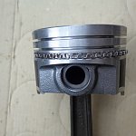
Here are the pistons that we are using for this 360 build, the higher compression 360 pistons that we hope will get us into the 9's for compression... We will check them later in the build to see where they come out...

Here's a view of the top of the piston showing the markings....

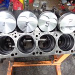
Now before you install the rings on the pistons, it's a good idea to verify that the rods are properly installed in the correct orientation... We found that one of our rods was pinned backwards and had to bring it to a machine shop to get corrected... A good way to do this is to put them on top of the engine block in order like this with the piston tops in the proper orientation...
*** Note that the anchor slots on the rods and caps go together on the same side... DO NOT PUT THEM ON OPPOSITE SIDES AS THIS MAY ALLOW THE ROD BEARING TO SPIN... ***
*** It is important to always put the caps on your rods and mains together... I say to myself and taught my son to say "anchor slot to anchor slot" while lining them up so you train yourself to mate them together properly... ***
For pistons that have only two "eyebrows"/valve reliefs, the eyebrows should be up so they are on the top of the cylinder... For pistons with 4 eyebrows or flat tops, some may have a notch on one side of the piston, this notch points/goes toward the front of the engine...
I like to put the pistons on the engine above each cylinder in the proper orientation with the eyebrows on top and check the squirt holes and anchor slots are in the proper orientation...

The squirt holes in the rod should point to the opposite cylinder/center of the engine when they are installed as they oil the cylinder on the opposite side of the one that they are in... Consequently, the anchor slots are pointing toward the outside of the block...

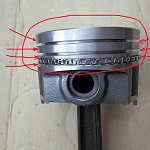
Here I have circled the oil squirt holes in red and the anchor slots in yellow... When checking the rod orientation this way the squirt holes should be on top and the anchor slots be on the bottom for them to be in the proper orientation...

Here's a closer view of them...

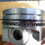
I had to change the anchor slot pointer color to blue here as the yellow blended in with the picture too much and didn't stand out...

Here's an even closer view showing the oil squirt hole and anchor slot orientation...


*************************************************************************
Prep the rings:
Ok now that we have verified that the rods and pistons are on correctly, it's time to install the rings...
Here's the box that the rings come in, I recommend keeping them in the box until you need them... Also note that on the side flaps on each side of the box tell you what groove the rings go in...

Here's the side for the two compression rings which go in the top two grooves of the piston...

Inside the box are the instructions for how to install the rings...
1. If there are dots on the rings, the dots should go toward the top of the piston...
2. If there is a bevel on the edge of the ring and no dot, the bevel should be installed so it faces the top of the ring...
3. If there is a groove on the outside edge of the ring, the groove should face down toward the bottom of the piston...
4. If there are no marks, dots, grooves, or bevels on the ring, it can be installed with either side up....

I recommend starting with the top ring... For our top ring here, there are no dots, grooves, bevels, so it can be installed with either side up...

For the compression rings, I like to knock off any sharp edges on both sides of the ring edges for the gap... This makes sure that there are no burrs or sharp edges that can score/groove the cylinder.... I use a small grinding stone to do that on all 4 sides of each edge of the ring for both sides...
Here is the grinding stone that I like to use, it's not too big and convenient to use... I have one out of the package and one in the package... I get them at Ace Hardware...

Here's a closer look of the package...

Here's a close up of the part number in case you want to get one for yourself...

Here is the grinding stone with the top ring...

Now use the stone to knock the sharp edges off the ring... Be sure to get all for corners of both sides of the ring...


Here is what it looks like after you chamfer the edges...

Get your tack cloth like we used to clean the bearings with and wipe the ring clean from any chips and debris from chamferring the edges of the rings with the grinding stone...


Here's what the tack cloth looks like opened up...

Wipe the rings like this...

*************************************************************************
Measure the ring gaps:
I start with the top compression ring first, then the second compression ring, and then the two thin oil rings; so when I have them all finished, they will be in the proper order to install them on the pistons...
First put all of the top rings in each bore with the ring gaps on the top side of the bore so you can easily measure them... Then use a piston without rings to push them down just past the bottom ring land like this... Do this for all 8 cylinders...
Here's starting to push them down...

Now push each ring down to about here in each cylinder for all 8 cylinders....

They should look like this.... The rings should be square in the bore now and both ends of the ring should be even... It is important to keep the ring square in the bore and both sides of the ring even to measure the gap accurately...

Now go to the back of the engine chapter 9 in the specifications section of a service manual and look up the spec for the ring gaps in the small block specification section... I believe that this is from a 71 service manual, you will see that the ring gap for all small blocks 318-340-360 is .010" - .020".... The gap for 273's should be the same, but are not listed in this manual as they were not made for this year that the service manual covers....
This means that the gap should be no smaller than .010" and no larger than .020"...

Here I have circled the ring gap spec for the compression ring in red
...

Now get your feeler gauge and flip out the .010" and .020" feeler gauges...


Take the .010" feeler gauge and check to make sure that the feeler gauge will fit between the two ends of the ring... This verifies that you meet the minimum gap... You have to be careful not to move either side of the ring as you have to keep both ends of the ring even to measure the gap properly... If you move either side of the ring, pull the ring up in the bore a little and take the piston to make it square and even again...

Then take the .020" feeler gauge and make sure that it won't go in the gap... If the .020" feeler gauge will fit in the gap, try the .021" feeler gauge... If the .021" feeler gauge does go in, then the ring gap is too large, you need to get the next step smaller ring, or you may use file fit rings to set the gap.... I am not going to get into file fit rings yet, but may update for them at a later time....

Do this for all 8 rings...
Now take the piston without any rings and push all 8 of the top rings deep into the cylinder bore almost to the bottom and keep them there... This will help you keep track of what ring goes to what cylinder... Once you measure the gap for each ring in a cylinder it becomes the ring for that cylinder... If you move the ring to another cylinder, then you need to measure the gap again to make sure that it has the proper gap in that cylinder in case there is any variation from one cylinder to the other...
Next take the second compression ring and do the same thing...

This set of rings has a dot on them for the middle/second compression ring, so the face with the dot on it should go towards the top of the cylinder...

Here's a closer look at the dot/dimple...

I have it circled here...

File both ends of the ring with the sharpening stone just like with the top ring...


Then use the tack cloth like before to clean any dirt and debris from the ends with the grinding stone before installing them in the bore of the engine...
Then install all 8 rings, one in each cylinder with the dimple/dot facing up and the gap at the top of the bore and push it down to the same level you did with the first ring... Make sure that the ring is square and even in the bore....

Here's about how deep you want to push it...

When all of them are in, they should look like this....

Since the gap is the same for both compression rings, use the same .010" and .020" feeler gauges to check the ring gaps as before....


If all the ring gaps check out good, then push the second compression ring to the bottom of the bore like before and stop just above the first ring... You don't have to push it to be touching the first ring, just a little above it will do... You are just keeping the rings in the bore that you have measured them in so they don't get mixed up... If you change the bore that the ring is in, you should check the gap again in that bore in case there are any differences from bore to bore... Once you get it measured in the bore, it should stay in that bore....
Now check the ring end gaps for the two thin oil rings...

Here is the spec for the thin oil rings, also called the oil rails... The gap is supposed to be .015" - .055"....

Take the .015" feeler gauge to measure the minimum gap so the .015" feeler gauge should fit between the two ends of the ring... Since they do not have a feeler gauge that is .055" thick, just take out two fat ones and stack them together to measure the max side of the gap.... I'm going to use the .032" + the .030" feeler gauges pressed together to measure to make sure the gap is too large... I can tell by experience that these will work as the gap is not that large with the rings after I put them in this engine... You can stack two or three together to get the maximum .055" thickness needed to check to be sure the gap is not too big...

You should have the point of how to check these by now so to keep this section from getting too long, I will not post pictures for checking the two oil rails, but you should be able follow the same procedure as above for them...
Install 8 of them like before in each cylinder and measure the gap, then push them down in the bore...
Use the .015" feeler gauge to make sure that the gap is not too small, and then stack some feeler gauges to .055" and check that the gap is not too big....
Repeat this for the second oil ring...
*************************************************************************
Install the rings on the pistons:
Ok, now it's time to put the rings on each piston...
You want to put the rings on the piston that is for that particular cylinder/bore... Take #1 piston and use the rings that you measured the gaps in from the #1 cylinder of the block... This is why we installed them and measured the gaps in that order, so they are in the proper order that we put them on the piston now...
They make a ring expander tool, but it can be awkward to use and sometimes the ring will slip off the tool and fly around the garage... The tool has no way to keep the ring even and it may tend to go upward or downward and then fly off... The ring when expanded will act like a spring and can go a long distance when this happens, so I prefer to install the rings by hand, even though the manufacturer does not recommend it, I feel that I have more control when doing it this way, you just have to be careful...
First take the center oil ring that is still in the box that they came in (the squiggly one) and put it in the bottom groove of the piston like this... The two ends should butt together, it's not hard to do....

Here you can see the two ends as the ring rests in the gap...

Here's the center oil ring installed on the piston....

Next take one of the thin oil rings/rails and carefully walk it down the piston until you can get it to go in the bottom of the middle oil ring that is already installed... Try not to let it go into the wrong groove or on top of the center ring as it will be more difficult to move it after that... Make sure that it settles in the proper position and be cautious that the ends of the ring don't scratch the piston while you are installing it...


Now do the same thing for the second thin oil rail and walk it down until it goes in the oil ring groove and is on the top side of the squiggly middle oil ring like this...


Now after all three rings are installed, grab them and make sure that they spin freely in the groove.... It is important that the rings are free to spin in their groove...
Now you want to orient your ring end gaps... The ring end gaps should not be aligned, you want them to be a minimum of 90° apart... I like to find the center ring gap and then put one of the thin rings at + 90° and the other thin ring gap at - 90° from the center ring gap...
After the all three oil rings are installed, the next ring is the second compression ring that goes in the middle ring groove of the piston... For this ring set the middle or second compression ring has a dot/dimple on the top and you want to make sure that you install the ring with the dot facing upwards towards the top of the piston....
This ring is thicker and not as flexible as the oil rings, so you have to be more careful when walking it down to it's proper groove... I find that it goes easier if you start one end first, then keep the other end above the top of the piston as you wrap the ring around the piston until you get it to the proper groove... Try not to let it set in the top groove on the way down as it will be more difficult to get it out of that one on the way to the second groove... My son had not perfected this technique yet as it's his first build, so the pictures do now show this particular method... You will see what I mean as you do a few yourself... Again, be careful not to let the ring ends scratch/score the high parts of the ring lands on the side of the piston as you walk it down to its groove....
Here he's doing it the beginner way which is a little more difficult, he should have one end above the top of the piston so he can spiral walk it down....

Here he's doing it the proper way... If one end of the second ring starts to go to the first ring groove, then make sure that you overshoot that groove with the other end and walk it down to the second groove...

Here is the second ring in its proper groove...


Now repeat the same procedure for the top compression ring... This top ring does not have any dimples or notches and can be installed either way... When the compression rings are both installed, check them to make sure that they rotate/spin freely by giving them a twist... Then after verifying that the rings can spin freely, rotate the rings so that the ring gaps are a minimum of 90° apart from each other...


Repeat this procedure for all 8 pistons... I like to put them in a box in the order that they go in the engine until I'm ready to install them in the engine...
*************************************************************************
Congratulations!!! You now have the rings installed on all of your pistons and are now ready to move onto section 7 - installing the pistons in the engine....
*************************************************************************
This is the next step to continue after Sections 1 - 5... If you missed them, you can find it here...
How to Rebuild a Small Block Part 1: Block Prep
How to Rebuild a Small Block Part 2: Cam Bearing Install
How to Rebuild a Small Block Part 3: Install Water Jacket and Oil Galley Plugs
How to Rebuild a Small Block Part 4: Pre Flight Inspection After Machine Shop Before Assembly
How to Rebuild a Small Block Part 5: Crankshaft Install
*************************************************************************
Hello everyone, it's Krazykuda here to show you how to rebuild a small block... This article is to help any newbies through rebuilding a small block Mopar LA engine, but may have a few tips that some of you seasoned builders may find useful... If you haven't ever built an engine, I will show you what you need to know to do it yourself...
The goal of this series is to show what you can do at home in your own garage... Go at your own pace and ability and then take it to someone knowledgeable for what you are not capable of doing yourself or don't have the proper equipment/tools for...
Keep checking back in from time to time as this is a work in progress and I plan to keep updating it as I build more engines and can show you more variations...
I am going to break this into sections that you can follow along with and make sense to do in 'stages' when you build... Plus you can then jump to the section that you are working on to help keep from sorting through one very long thread to find what part that you are working on when you are doing it....
*************************************************************************
*** Important Note *** Sometimes things may not go right and you will run into a snag/road block... Do not get in a hurry to finish and take short cuts that may compromise your build...
Step back, take a break, and think about it for a while... Or seek help from other experienced people or professionals to overcome the problem... Do it right and don't take any unnecessary chances that may compromise the integrity of your build...
If you don't fix the problem correctly, it may come back to haunt you and cost even more time and money than if you took the time to think about it and research it to fix the problem correctly...
This has been a public service announcement from krazykuda....
*************************************************************************
I like to start my engine builds by getting one of the Mancini Racing engine rebuild kits... They offer 4 different kits with 2 manufacturers, one set from Sealed Power, and the other from Clevite... They offer both manufacturer's kits in stages: A, B, C, and D...
Kit's A and B come with:
Rod and main bearings, rings, and Fel Pro complete gasket kit...
Kit A comes with cast rings and runs between $200 - $210 depending on engine size...
Kit B comes with moly rings and runs between $205 - $230 depending on engine size...
Kit C comes with: Rod, main, and cam bearings, Fel Pro complete gasket kit, moly rings, freeze plugs, Melling oil pump, and cast pistons with varying prices that are reasonable... The cast pistons in this kit are the low compression ones, but you can call them and have them substitute the higher compression pistons for the difference in cost... They did this for us for our 360 and we were able to get the higher compression H116CP pistons for our 360 which will get us closer to 9's for compression vs in the 8's for the standard ones that come in the kit...
Kit D comes with everything in kit C, but forged pistons and costs a little more, but not available in all engine sizes... However the Sealed power kit D only is offered in 340, where the Clevite kit is offered for both 340 and 360 engines....
All of the kits A - D in the Clevite still have the Fel Pro complete engine gasket kit and Sealed Power rings, but have Clevite bearings...
Here is the main page listing all of the engine kits:
Engine Rebuild Kits
These kits are all reasonably priced and are a good starting point for a rebuild...
The Sealed Power/Federal Mogul freeze plug kit doesn't come with all of the oil galley plugs, but only has the two oil galley plugs that go behind the camshaft thrust plate...
However Mancini has their own freeze plug kit that comes with all of the freeze plugs and all of the oil galley plugs except the one that goes under the rear main bearing cap... You can ask them to substitute the Mancini Racing plug kit for the difference in price between the Sealed Power kit...
Here's the Mancini Racing brass engine plug kit...
Here are all of the plugs laid out, but I believe one is missing that I may have "stolen/scavenged" for another engine....
*************************************************************************
Now before we begin, I want to caution you to be very careful when handling pistons... Treat them like they are egg shells as they are very delicate and you want to protect the ring lands and skirts from any sharp blows... It doesn't take much force to damage the ring land and 'smash' or dent it to close it down and prevent the ring from going into the groove... You need to make sure that the ring lands are dent/ding/burr free and the rings can spin/rotate freely when the rings are installed...
If you do damage a ring land, you may be able to use a small fine metal file to repair it, but keep in mind that it's difficult to get the proper surface finish if you file them which may not let them rotate as easily as a fresh machined one...
*************************************************************************
Here are the pistons that we are using for this 360 build, the higher compression 360 pistons that we hope will get us into the 9's for compression... We will check them later in the build to see where they come out...
Here's a view of the top of the piston showing the markings....
Now before you install the rings on the pistons, it's a good idea to verify that the rods are properly installed in the correct orientation... We found that one of our rods was pinned backwards and had to bring it to a machine shop to get corrected... A good way to do this is to put them on top of the engine block in order like this with the piston tops in the proper orientation...
*** Note that the anchor slots on the rods and caps go together on the same side... DO NOT PUT THEM ON OPPOSITE SIDES AS THIS MAY ALLOW THE ROD BEARING TO SPIN... ***
*** It is important to always put the caps on your rods and mains together... I say to myself and taught my son to say "anchor slot to anchor slot" while lining them up so you train yourself to mate them together properly... ***
For pistons that have only two "eyebrows"/valve reliefs, the eyebrows should be up so they are on the top of the cylinder... For pistons with 4 eyebrows or flat tops, some may have a notch on one side of the piston, this notch points/goes toward the front of the engine...
I like to put the pistons on the engine above each cylinder in the proper orientation with the eyebrows on top and check the squirt holes and anchor slots are in the proper orientation...
The squirt holes in the rod should point to the opposite cylinder/center of the engine when they are installed as they oil the cylinder on the opposite side of the one that they are in... Consequently, the anchor slots are pointing toward the outside of the block...
Here I have circled the oil squirt holes in red and the anchor slots in yellow... When checking the rod orientation this way the squirt holes should be on top and the anchor slots be on the bottom for them to be in the proper orientation...
Here's a closer view of them...
I had to change the anchor slot pointer color to blue here as the yellow blended in with the picture too much and didn't stand out...
Here's an even closer view showing the oil squirt hole and anchor slot orientation...
*************************************************************************
Prep the rings:
Ok now that we have verified that the rods and pistons are on correctly, it's time to install the rings...
Here's the box that the rings come in, I recommend keeping them in the box until you need them... Also note that on the side flaps on each side of the box tell you what groove the rings go in...
Here's the side for the two compression rings which go in the top two grooves of the piston...
Inside the box are the instructions for how to install the rings...
1. If there are dots on the rings, the dots should go toward the top of the piston...
2. If there is a bevel on the edge of the ring and no dot, the bevel should be installed so it faces the top of the ring...
3. If there is a groove on the outside edge of the ring, the groove should face down toward the bottom of the piston...
4. If there are no marks, dots, grooves, or bevels on the ring, it can be installed with either side up....
I recommend starting with the top ring... For our top ring here, there are no dots, grooves, bevels, so it can be installed with either side up...
For the compression rings, I like to knock off any sharp edges on both sides of the ring edges for the gap... This makes sure that there are no burrs or sharp edges that can score/groove the cylinder.... I use a small grinding stone to do that on all 4 sides of each edge of the ring for both sides...
Here is the grinding stone that I like to use, it's not too big and convenient to use... I have one out of the package and one in the package... I get them at Ace Hardware...
Here's a closer look of the package...
Here's a close up of the part number in case you want to get one for yourself...
Here is the grinding stone with the top ring...
Now use the stone to knock the sharp edges off the ring... Be sure to get all for corners of both sides of the ring...
Here is what it looks like after you chamfer the edges...
Get your tack cloth like we used to clean the bearings with and wipe the ring clean from any chips and debris from chamferring the edges of the rings with the grinding stone...
Here's what the tack cloth looks like opened up...
Wipe the rings like this...
*************************************************************************
Measure the ring gaps:
I start with the top compression ring first, then the second compression ring, and then the two thin oil rings; so when I have them all finished, they will be in the proper order to install them on the pistons...
First put all of the top rings in each bore with the ring gaps on the top side of the bore so you can easily measure them... Then use a piston without rings to push them down just past the bottom ring land like this... Do this for all 8 cylinders...
Here's starting to push them down...
Now push each ring down to about here in each cylinder for all 8 cylinders....
They should look like this.... The rings should be square in the bore now and both ends of the ring should be even... It is important to keep the ring square in the bore and both sides of the ring even to measure the gap accurately...
Now go to the back of the engine chapter 9 in the specifications section of a service manual and look up the spec for the ring gaps in the small block specification section... I believe that this is from a 71 service manual, you will see that the ring gap for all small blocks 318-340-360 is .010" - .020".... The gap for 273's should be the same, but are not listed in this manual as they were not made for this year that the service manual covers....
This means that the gap should be no smaller than .010" and no larger than .020"...
Here I have circled the ring gap spec for the compression ring in red
...
Now get your feeler gauge and flip out the .010" and .020" feeler gauges...
Take the .010" feeler gauge and check to make sure that the feeler gauge will fit between the two ends of the ring... This verifies that you meet the minimum gap... You have to be careful not to move either side of the ring as you have to keep both ends of the ring even to measure the gap properly... If you move either side of the ring, pull the ring up in the bore a little and take the piston to make it square and even again...
Then take the .020" feeler gauge and make sure that it won't go in the gap... If the .020" feeler gauge will fit in the gap, try the .021" feeler gauge... If the .021" feeler gauge does go in, then the ring gap is too large, you need to get the next step smaller ring, or you may use file fit rings to set the gap.... I am not going to get into file fit rings yet, but may update for them at a later time....
Do this for all 8 rings...
Now take the piston without any rings and push all 8 of the top rings deep into the cylinder bore almost to the bottom and keep them there... This will help you keep track of what ring goes to what cylinder... Once you measure the gap for each ring in a cylinder it becomes the ring for that cylinder... If you move the ring to another cylinder, then you need to measure the gap again to make sure that it has the proper gap in that cylinder in case there is any variation from one cylinder to the other...
Next take the second compression ring and do the same thing...
This set of rings has a dot on them for the middle/second compression ring, so the face with the dot on it should go towards the top of the cylinder...
Here's a closer look at the dot/dimple...
I have it circled here...
File both ends of the ring with the sharpening stone just like with the top ring...
Then use the tack cloth like before to clean any dirt and debris from the ends with the grinding stone before installing them in the bore of the engine...
Then install all 8 rings, one in each cylinder with the dimple/dot facing up and the gap at the top of the bore and push it down to the same level you did with the first ring... Make sure that the ring is square and even in the bore....
Here's about how deep you want to push it...
When all of them are in, they should look like this....
Since the gap is the same for both compression rings, use the same .010" and .020" feeler gauges to check the ring gaps as before....
If all the ring gaps check out good, then push the second compression ring to the bottom of the bore like before and stop just above the first ring... You don't have to push it to be touching the first ring, just a little above it will do... You are just keeping the rings in the bore that you have measured them in so they don't get mixed up... If you change the bore that the ring is in, you should check the gap again in that bore in case there are any differences from bore to bore... Once you get it measured in the bore, it should stay in that bore....
Now check the ring end gaps for the two thin oil rings...
Here is the spec for the thin oil rings, also called the oil rails... The gap is supposed to be .015" - .055"....
Take the .015" feeler gauge to measure the minimum gap so the .015" feeler gauge should fit between the two ends of the ring... Since they do not have a feeler gauge that is .055" thick, just take out two fat ones and stack them together to measure the max side of the gap.... I'm going to use the .032" + the .030" feeler gauges pressed together to measure to make sure the gap is too large... I can tell by experience that these will work as the gap is not that large with the rings after I put them in this engine... You can stack two or three together to get the maximum .055" thickness needed to check to be sure the gap is not too big...
You should have the point of how to check these by now so to keep this section from getting too long, I will not post pictures for checking the two oil rails, but you should be able follow the same procedure as above for them...
Install 8 of them like before in each cylinder and measure the gap, then push them down in the bore...
Use the .015" feeler gauge to make sure that the gap is not too small, and then stack some feeler gauges to .055" and check that the gap is not too big....
Repeat this for the second oil ring...
*************************************************************************
Install the rings on the pistons:
Ok, now it's time to put the rings on each piston...
You want to put the rings on the piston that is for that particular cylinder/bore... Take #1 piston and use the rings that you measured the gaps in from the #1 cylinder of the block... This is why we installed them and measured the gaps in that order, so they are in the proper order that we put them on the piston now...
They make a ring expander tool, but it can be awkward to use and sometimes the ring will slip off the tool and fly around the garage... The tool has no way to keep the ring even and it may tend to go upward or downward and then fly off... The ring when expanded will act like a spring and can go a long distance when this happens, so I prefer to install the rings by hand, even though the manufacturer does not recommend it, I feel that I have more control when doing it this way, you just have to be careful...
First take the center oil ring that is still in the box that they came in (the squiggly one) and put it in the bottom groove of the piston like this... The two ends should butt together, it's not hard to do....
Here you can see the two ends as the ring rests in the gap...
Here's the center oil ring installed on the piston....
Next take one of the thin oil rings/rails and carefully walk it down the piston until you can get it to go in the bottom of the middle oil ring that is already installed... Try not to let it go into the wrong groove or on top of the center ring as it will be more difficult to move it after that... Make sure that it settles in the proper position and be cautious that the ends of the ring don't scratch the piston while you are installing it...
Now do the same thing for the second thin oil rail and walk it down until it goes in the oil ring groove and is on the top side of the squiggly middle oil ring like this...
Now after all three rings are installed, grab them and make sure that they spin freely in the groove.... It is important that the rings are free to spin in their groove...
Now you want to orient your ring end gaps... The ring end gaps should not be aligned, you want them to be a minimum of 90° apart... I like to find the center ring gap and then put one of the thin rings at + 90° and the other thin ring gap at - 90° from the center ring gap...
After the all three oil rings are installed, the next ring is the second compression ring that goes in the middle ring groove of the piston... For this ring set the middle or second compression ring has a dot/dimple on the top and you want to make sure that you install the ring with the dot facing upwards towards the top of the piston....
This ring is thicker and not as flexible as the oil rings, so you have to be more careful when walking it down to it's proper groove... I find that it goes easier if you start one end first, then keep the other end above the top of the piston as you wrap the ring around the piston until you get it to the proper groove... Try not to let it set in the top groove on the way down as it will be more difficult to get it out of that one on the way to the second groove... My son had not perfected this technique yet as it's his first build, so the pictures do now show this particular method... You will see what I mean as you do a few yourself... Again, be careful not to let the ring ends scratch/score the high parts of the ring lands on the side of the piston as you walk it down to its groove....
Here he's doing it the beginner way which is a little more difficult, he should have one end above the top of the piston so he can spiral walk it down....
Here he's doing it the proper way... If one end of the second ring starts to go to the first ring groove, then make sure that you overshoot that groove with the other end and walk it down to the second groove...
Here is the second ring in its proper groove...
Now repeat the same procedure for the top compression ring... This top ring does not have any dimples or notches and can be installed either way... When the compression rings are both installed, check them to make sure that they rotate/spin freely by giving them a twist... Then after verifying that the rings can spin freely, rotate the rings so that the ring gaps are a minimum of 90° apart from each other...
Repeat this procedure for all 8 pistons... I like to put them in a box in the order that they go in the engine until I'm ready to install them in the engine...
*************************************************************************
Congratulations!!! You now have the rings installed on all of your pistons and are now ready to move onto section 7 - installing the pistons in the engine....
*************************************************************************