In this chapter I am going to go through installing the pistons in the block... In the last chapter I showed you how to install the rings on the pistons... Now it's time to install them, or as we used to call it back in the engine factory "shoot the pistons" into the block...
This is the next step to continue after Sections 1 - 6... If you missed them, you can find it here...
How to Rebuild a Small Block Part 1: Block Prep
How to Rebuild a Small Block Part 2: Cam Bearing Install
How to Rebuild a Small Block Part 3: Install Water Jacket and Oil Galley Plugs
How to Rebuild a Small Block Part 4: Pre Flight Inspection After Machine Shop Before Assembly
How to Rebuild a Small Block Part 5: Crankshaft Install
How to Rebuild a Small Block Part 6: Installing Rings on Pistons
*************************************************************************
Hello everyone, it's Krazykuda here to show you how to rebuild a small block... This article is to help any newbies through rebuilding a small block Mopar LA engine, but may have a few tips that some of you seasoned builders may find useful... If you haven't ever built an engine, I will show you what you need to know to do it yourself...
The goal of this series is to show what you can do at home in your own garage... Go at your own pace and ability and then take it to someone knowledgeable for what you are not capable of doing yourself or don't have the proper equipment/tools for...
Keep checking back in from time to time as this is a work in progress and I plan to keep updating it as I build more engines and can show you more variations...
I am going to break this into sections that you can follow along with and make sense to do in 'stages' when you build... Plus you can then jump to the section that you are working on to help keep from sorting through one very long thread to find what part that you are working on when you are doing it....
*************************************************************************
*** Important Note *** Sometimes things may not go right and you will run into a snag/road block... Do not get in a hurry to finish and take short cuts that may compromise your build...
Step back, take a break, and think about it for a while... Or seek help from other experienced people or professionals to overcome the problem... Do it right and don't take any unnecessary chances that may compromise the integrity of your build...
If you don't fix the problem correctly, it may come back to haunt you and cost even more time and money than if you took the time to think about it and research it to fix the problem correctly...
This has been a public service announcement from krazykuda....
*************************************************************************
Keep everything clean and don't mix and match caps and rods...
Ok, right now we have the rings on all of the pistons... Now we need to install them into the block...
Before we get too deep into this I want to point out it is important that you keep each cap with it's original rod... They were machined as a set and if you mix them up, the bore for the crank journal may not line up properly and cause a tight or locked up crankshaft... YOU CANNOT MIX AND MATCH RODS AND CAPS...
The second thing to point out is you have to keep them very clean, like hospital clean... I've seen the smallest of things cause interference with the crank and bearings like a small piece of dirt, fuzz, string from a cotton glove or shop rag get on the bearing or behind the bearing where it makes the crank tight or even prevent it from rotating....
*************************************************************************
Prepping the pistons to install...
I like to have squirt holes in my rods... The squirt hole squirts oil on the cylinder on the opposite side of the one it's in... Some aftermarket rods do not have squirt holes, but I prefer to buy new connecting rod bolts and nuts and have them installed on the rods and the rod reconditioned where they re-do the crank bore on the rod...
When you remove the original rod bolts, the new bolts may not go back into the same position that the original bolt was in and the bore of the cap and rod may not be lined up... This mis-match can cause the rod and cap to be tight and cause more drag, wear, or even prevent the crank from turning in extreme cases, so you should always get the rod and cap reconditioned when changing the rod bolts...
When they recondition the crank bore end of the rod, they remove the bolts from the rod, then resurface the flat face that mates together on both the cap and rod... Then they install the new rod bolts and torque the caps to full torque and re-bore the crankshaft bore so it is now true and round like it should be...
It is important to replace the rod bolts on used rods because every time the bolts are torqued there is a small amount of permanent stretch in them (typically .001 - .0025")... If you torque the rod bolts too many times, they can be overstretched and weaken the bolt... Under the constant cycling of the crank spinning the bolts can fatigue and break causing you to throw a rod which most likely will break the block in the process and you will have to start all over again with a new block, crank, and rod(s)... So it's cheap insurance to replace the rod bolts if you are going to re-use the factory rods... It's worth the money as it will cost alot more if they let loose... You can get replacement rod bolts from Mancini Racing...
ARP High Perf. Connecting Rod Bolt Kit
When I worked in the engine factory, Engine Design and Fastener Engineering allowed us 5 clamp cycles maximum on the rod bolts before we had to scrap the rods.... One cycle was used to assemble the cap and rod together on the rod machining line to machine the crankshaft bore of the rod... Then we used a second clamp cycle when we installed the pistons in the engine... A third cycle was allowed for a repair in the engine factory before we had to scrap the rod... (We were only allowed to recycle a piston/rod assembly only once)... We saved two clamp cycles for "outside the factory", one for service, and the other for a rebuild (however they didn't account for plastic gauge)...
*************************************************************************
How to Identify Your Current Bearings...
If you aren't sure what size bearings that you need for your build, you can find out from the back of the old bearing if you are just replacing them with the same size and not getting the crankshaft cut... Most manufacturers mark/stamp the information on the back of the bearings...

This part shows the size of the bearings, this one is for our engine where our crank is cut .001" under size...

Here is the date code for the bearing, it has the month and year of production... This set was made in the 12th month (December) and in 2017...

Here you can see the top part is the part number and manufacturer, Federal Mogul who makes sealed power.... The bottom numbers identify what batch/lot the bearings were made in... This is used for traceability in case there are any defects, they can sort out the suspect ones from the good ones once they figure out when and how long that the defect was made... This way they can sort out any bad ones from the good ones instead of scrapping out everything and having to start all over... They can save money from having to scrap any good ones...

*************************************************************************
Squirt Holes vs No Squirt Holes...
Some bearings are made with the "notch" for the oil squirt hole, and some aren't... If you are using rods with the oil squirt holes, make sure that you get the proper rod bearings...
The Clevite bearings that came with our engine refresh kit from Mancini did not have the notch/hole for the oil squirt holes... When I called them to exchange them for ones with squirt holes, they claimed that none of their bearings they carried had the notch for the squirt holes... I don't think that the guy I was talking to was was aware that Sealed Power makes bearings with the squirt holes as I was able to get a set from Summit Racing that had them with squirt holes and Mancini racing carries Sealed Power...
We ended up ordering a set of Sealed Power bearings from Summit Racing and they had the holes for the oil squirt holes in the rod... I requested that they have someone personally inspect the bearings before shipping them so we didn't waste our time getting the wrong ones again...
Our engine had a crank that was turned/cut .001", so all of the bearings shown are for this size crank journal...
Here are the Clevite bearings without the squirt hole notch...


Here are the Sealed Power bearings with the squirt hole notches....


*************************************************************************
Install the Rod Bearings...
Make sure to mark each rod and cap so you can mate them back together with their original "partner"....
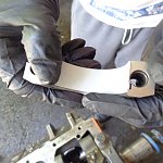
Now separate the caps from the rods... Make sure that they are marked so you can get the caps mated back to the proper rod that they were machined on... After separating the caps from the rod, install the bearings in the rod and cap like this....
Put the tab/anchor slot in the bearing in the anchor slot notch of the rod and then push the other side down until each end of the bearings are even with the flat surface of the rod.... Be sure to wipe the rod bore and the back surface of the bearing with tack cloth like we did in the crankshaft install chapter to remove any dust/dirt/debris from the surfaces before installing the bearings....

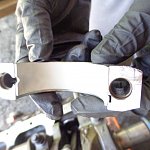
It should look like this when they are installed...

Next do the bearing in the cap the same way... Make sure to keep the cap and rods together as a set like I mentioned before...
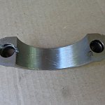
Here you can see the groove in the rod cap for the oil squirt hole...


Line up the anchor slot tab in the bearing with the anchor slot groove in the cap and press the bearing in until both ends are even with the ends of the cap...


*************************************************************************
Protect the Rod Bolt Threads From the Crank...
I like to get some spare 3/8" hose and cut it into 3" - 4" lengths... These are used to cover the threads on the rod bolts so they don't harm the crank during installation... Do a minimum of 4 pieces for two rods, or you can do 16 pieces so you can install them on all 8 pistons so they are all ready to install...
Like this...


Now install the rubber hose pieces on the rod bolts to cover the threads and keep them from nicking or scratching the crankshaft journals while installing them....
I forgot to get a picture of the hose installed on the pistons before compressing the rings, so please excuse the ring compressor in this picture and pay attention to the hoses on the ends of the rod bolts... You don't have to put them all the way down, just enough to cover the threads on the bolts to keep them from damaging your crank when shooting the pistons...

*************************************************************************
Compress the Rings...
I made a tool box for installing pistons... It has grinding stones, plastic gauge, ring compressors, ring expanders, ring files, and feeler gauges... It comes in handy when building engines...


Pick up the pistons and give the rings a twist to make sure that they move freely and can spin in their grooves...


Then set the ring gaps, the ring gaps should be a minimum of 90° apart from each other for both the oil rings, and the compression rings... I like to set the first thin oil ring gap 90° apart from the middle oil ring ends, and then the other thin oil ring another 90° in the opposite direction so the thin oil ring gaps are 180° apart...
It's difficult to show the oil rings in the same shot, but here's a shot of one showing that the rest of the ring gaps are not in line...


Next check the two top compression rings to make sure the gaps are also a minimum of 90° apart... I try to go for 180° for maximum effect... This way the air has to move farther from one ring gap to the other to leak any pressure... I set them at 90° for this picture so I could get them in the same view...


*************************************************************************
Install the ring compressor...
Now slide the ring compressor over the piston like this... Pay attention to the orientation for the compressor as there are dimples on the bottom to keep it from going into the bore while installing the piston... You also want the square drive hole used to tighten the "sleeve" on the piston to face upwards...

Slide the bottom of the sleeve so it is just below the bottom oil rings on the piston... You want the piston skirt exposed as that helps you align the piston to the bore...

Here I have the dimples on the sleeve highlighted.... These bottom out on the top of the block to keep the sleeve from going into the cylinder when sliding the piston in...

You will need to use this tab on the side of the sleeve when loosening and tightening the sleeve on the piston... It takes a little practice at first, but you will get used to it after a few times... You have to hold it still when opening and closing the sleeve...

In these next two pictures you need to see that the square drive for tightening the sleeve is facing upward and you have the sleeve as tight as you can around the piston... If there are any gaps, the rings will not be compressed enough and they will hang up on the block...


Here the ring compressor sleeve is too far down and covers the whole piston skirt....

You also want to make the sleeve of the ring compressor square and even with itself... You don't want to accordion it like this...


Once you get the ring compressing tool properly positioned and tightened, you are ready to install the pistons into the engine...
*************************************************************************
Shooting the Pistons...
Rotate the crankshaft so the rod journal that you are working on is at Bottom Dead Center (BDC) as far away from the bore as it can be... Then spray the journal with parts cleaner and wipe the journal clean with a shop rag followed by the tack cloth to make sure it's good and clean without any lint, dust, dirt, or debris on the journal... Then clean the bearing in the rod the same way with parts cleaner, shop rag, and tack cloth before shooting the piston in the bore...

The piston and rod assembly should have the two pieces of hose on the rod bolts, the sleeve of the ring compressor should be tight and even before you put it in the block...
I like to clean and lube the cylinder bores before installing each set of pistons... Spray them with parts cleaner and wipe them clean with a shop rag, then go over them with the tack cloth to make sure that they are perfectly clean... Then pour some STP or Motor Honey in the bore and spread it around with your hand before shooting the pistons... You can clean and lube all 8 cylinders at the same time if you are going to install all of the pistons right away... This way you don't have to keep cleaning the heavy oil off your hands for each set of cylinders... You can tell that the STP and Motor Honey are good thick lubes as it's hard to clean off your hands afterwards... That's why we are using it...
Just before you put the piston in, check the top of the piston and make sure the the piston is oriented correctly with the two eyebrows are toward the top of the cylinder or the notch at the front of the piston is facing the front of the engine if the piston has a notch to mark which way goes to the front... The anchor slot should be on the outside facing you and the squirt hole should be facing the center of the engine away from you...
Do not use anything metal to drive the piston in the block because it can shatter or crack the piston....... It may be easier to use the wooden handle or rubber at the end of the handle of the mallet to help tap the top of the piston to start the piston in the bore... Keep the sleeve of the ring compressing tool all the way up to the block when tapping the piston in...
If you let the ring compressing sleeve come away from the block a ring may expand in the gap and keep you from pushing it in... Do not force it in, if it hangs up take the piston back out and reset the ring compressor and try again... It takes a little patience and practice to get it right, it still happens to me... If you try to force it in when the ring hangs up, you can shatter or crack the ring...
As soon as you get the top of the piston inside the bore even with the top of the head face of the block, stop and line up the two pieces of rubber hose that we put on the rod bolts so one is on each side of the crank journal... It's best to have the crank journal at Bottom Dead Center (BDC) while installing the piston...

Then continue tapping the piston up the bore with the wood and rubber mallet... The wood helps reach the piston as it gets deeper in the bore and cushions any sharp blows to the piston.... Keep tapping it up until you hear it hit the crank journal, it will make a distinctive thunk... Check the bearing shell in the rod to make sure it hasn't moved and is still fully seated in the rod...

Once the piston is all the way in, remove the rubber hose from both rod bolts with a pair of needle nosed pliers...

Now the piston is fully up to the crank and the hoses are off the rod bolts like this...

Next take a small piece of plastic gauge that is almost the width of the rod and place it across the top of the crank journal like this...

Then wipe the bearing in the cap with a tack cloth and carefully put the cap on the rod making sure the plastic gauge or bearing shell do not move while seating the cap...

Now snug both rod bolts, I find it's easier to run them down with a 3/8" ratchet and socket first...


After snugging the rod bolts, use a torque wrench and torque the rod nuts to 45 foot pounds making sure to pull the torque wrench slowly and evenly... To not yank or snap the wrench as then the torque will not be accurate... Slow and steady is the key to get accurate torque....

Here is the small block torque specs from the 71 Plymouth Service Manual... You will see that the recommended torque for the rod bolt nuts is 45 foot pounds...


Then after torquing both rod nuts, loosen them and remove the cap from the rod...
Here the recommended clearance for the rod bearings is .0005" - .0020" with a maximum allowed of .0025" from the 71 Plymouth Service Manual...


You will see the plastic gauge is now smashed like this... Use the marks on the plastic gauge sleeve to measure the clearance like this....


If it's too light to see on the crank, you can also check the plastic gauge on the rod cap...


After checking the clearance with the marks on the sleeve of the plastic gauge, then clean the plastic gauge off the crank and bearing in the rod cap with parts cleaner and a shop rag, then wipe it with the tack cloth to be sure there is no dirt, fuzz, or debris on both the crank and bearing... Then install the cap on the rod and put the nuts on finger tight to keep them together until you are finished with the other piston on the opposite cylinder...
Repeat the same process with the piston in the cylinder across from the one that you just finished... Then after you are done cleaning the plastic gauge off the crank and rod bearing, push both pistons and rod assemblies down about 1/4" and drizzle some STP or motor honey on the journal and let it run down and cover the whole crank journal and bearing in the rod...


It helps to hold the rods off the crank a little like this so the Motor Honey or STP can run down and fully coat the journal and rod bearing...


Then install the caps on the proper rods making sure not to mix them up... Snug the caps down with a ratchet and then torque them to spec of 45 foot pounds again.... Now these two cylinders are done and permanently torqued... Always go back and double check the torques to be sure that they are good... Checking the torque does not add any more stretch to the bolts because you are not loosening them again... You can double check the torques as many times as you wish once they are tightened as this will not add an additional clamp cycle... If you have a partner helping you, have them check the torques also... Remember to pull slowly and evenly when torquing, do not snap, tug, or yank the torque wrench or the torque may not be accurate....
Now rotate the crank so the journal for the next set of pistons is at BDC and repeat this process again... You should be able to rotate the crank by hand by using the counter weight on the crank until you get about 4 of the pistons in... Every set of pistons will add more drag to turn the crank... After installing 4 pistons you may need to use a socket and wrench to move the crank...
Keep repeating this process until all of the pistons are installed...
If all of the pistons are in and the crank won't turn with a wrench on it, go back and loosen one rod at a time until it loosens up.... Most likely it's one of the last ones that you did that's hanging it up... If loosening one rod allows the crank to turn much easier, then take the cap all the way off and inspect the bearing and journal to see if there are any marks or dirt or fuzz on it... If you find any, clean it and reinstall the rod cap to see if that made it any better... But don't loosen a rod cap once you have assembled it for the last time unless it's necessary because you will then add another clamp load on the rod bolt and give it some more permanent stretch...
When all of the pistons are installed and tightened, the crank should be able to be turned with a socket and wrench with some resistance... If everything feels good after all of the pistons are done, then move onto the next chapter and install the camshaft and timing chain....
Make sure to lube each set of rods with the STP or Motor Honey after plastic gauging them to keep them lubed during the rest of the engine build and for the first start of the engine...
*************************************************************************
Congratulations, you now have all of the pistons, now called a short block at this stage, and are ready to move onto the next section on installing the camshaft and timing chain...
*************************************************************************
This is the next step to continue after Sections 1 - 6... If you missed them, you can find it here...
How to Rebuild a Small Block Part 1: Block Prep
How to Rebuild a Small Block Part 2: Cam Bearing Install
How to Rebuild a Small Block Part 3: Install Water Jacket and Oil Galley Plugs
How to Rebuild a Small Block Part 4: Pre Flight Inspection After Machine Shop Before Assembly
How to Rebuild a Small Block Part 5: Crankshaft Install
How to Rebuild a Small Block Part 6: Installing Rings on Pistons
*************************************************************************
Hello everyone, it's Krazykuda here to show you how to rebuild a small block... This article is to help any newbies through rebuilding a small block Mopar LA engine, but may have a few tips that some of you seasoned builders may find useful... If you haven't ever built an engine, I will show you what you need to know to do it yourself...
The goal of this series is to show what you can do at home in your own garage... Go at your own pace and ability and then take it to someone knowledgeable for what you are not capable of doing yourself or don't have the proper equipment/tools for...
Keep checking back in from time to time as this is a work in progress and I plan to keep updating it as I build more engines and can show you more variations...
I am going to break this into sections that you can follow along with and make sense to do in 'stages' when you build... Plus you can then jump to the section that you are working on to help keep from sorting through one very long thread to find what part that you are working on when you are doing it....
*************************************************************************
*** Important Note *** Sometimes things may not go right and you will run into a snag/road block... Do not get in a hurry to finish and take short cuts that may compromise your build...
Step back, take a break, and think about it for a while... Or seek help from other experienced people or professionals to overcome the problem... Do it right and don't take any unnecessary chances that may compromise the integrity of your build...
If you don't fix the problem correctly, it may come back to haunt you and cost even more time and money than if you took the time to think about it and research it to fix the problem correctly...
This has been a public service announcement from krazykuda....
*************************************************************************
Keep everything clean and don't mix and match caps and rods...
Ok, right now we have the rings on all of the pistons... Now we need to install them into the block...
Before we get too deep into this I want to point out it is important that you keep each cap with it's original rod... They were machined as a set and if you mix them up, the bore for the crank journal may not line up properly and cause a tight or locked up crankshaft... YOU CANNOT MIX AND MATCH RODS AND CAPS...
The second thing to point out is you have to keep them very clean, like hospital clean... I've seen the smallest of things cause interference with the crank and bearings like a small piece of dirt, fuzz, string from a cotton glove or shop rag get on the bearing or behind the bearing where it makes the crank tight or even prevent it from rotating....
*************************************************************************
Prepping the pistons to install...
I like to have squirt holes in my rods... The squirt hole squirts oil on the cylinder on the opposite side of the one it's in... Some aftermarket rods do not have squirt holes, but I prefer to buy new connecting rod bolts and nuts and have them installed on the rods and the rod reconditioned where they re-do the crank bore on the rod...
When you remove the original rod bolts, the new bolts may not go back into the same position that the original bolt was in and the bore of the cap and rod may not be lined up... This mis-match can cause the rod and cap to be tight and cause more drag, wear, or even prevent the crank from turning in extreme cases, so you should always get the rod and cap reconditioned when changing the rod bolts...
When they recondition the crank bore end of the rod, they remove the bolts from the rod, then resurface the flat face that mates together on both the cap and rod... Then they install the new rod bolts and torque the caps to full torque and re-bore the crankshaft bore so it is now true and round like it should be...
It is important to replace the rod bolts on used rods because every time the bolts are torqued there is a small amount of permanent stretch in them (typically .001 - .0025")... If you torque the rod bolts too many times, they can be overstretched and weaken the bolt... Under the constant cycling of the crank spinning the bolts can fatigue and break causing you to throw a rod which most likely will break the block in the process and you will have to start all over again with a new block, crank, and rod(s)... So it's cheap insurance to replace the rod bolts if you are going to re-use the factory rods... It's worth the money as it will cost alot more if they let loose... You can get replacement rod bolts from Mancini Racing...
ARP High Perf. Connecting Rod Bolt Kit
When I worked in the engine factory, Engine Design and Fastener Engineering allowed us 5 clamp cycles maximum on the rod bolts before we had to scrap the rods.... One cycle was used to assemble the cap and rod together on the rod machining line to machine the crankshaft bore of the rod... Then we used a second clamp cycle when we installed the pistons in the engine... A third cycle was allowed for a repair in the engine factory before we had to scrap the rod... (We were only allowed to recycle a piston/rod assembly only once)... We saved two clamp cycles for "outside the factory", one for service, and the other for a rebuild (however they didn't account for plastic gauge)...
*************************************************************************
How to Identify Your Current Bearings...
If you aren't sure what size bearings that you need for your build, you can find out from the back of the old bearing if you are just replacing them with the same size and not getting the crankshaft cut... Most manufacturers mark/stamp the information on the back of the bearings...
This part shows the size of the bearings, this one is for our engine where our crank is cut .001" under size...
Here is the date code for the bearing, it has the month and year of production... This set was made in the 12th month (December) and in 2017...
Here you can see the top part is the part number and manufacturer, Federal Mogul who makes sealed power.... The bottom numbers identify what batch/lot the bearings were made in... This is used for traceability in case there are any defects, they can sort out the suspect ones from the good ones once they figure out when and how long that the defect was made... This way they can sort out any bad ones from the good ones instead of scrapping out everything and having to start all over... They can save money from having to scrap any good ones...
*************************************************************************
Squirt Holes vs No Squirt Holes...
Some bearings are made with the "notch" for the oil squirt hole, and some aren't... If you are using rods with the oil squirt holes, make sure that you get the proper rod bearings...
The Clevite bearings that came with our engine refresh kit from Mancini did not have the notch/hole for the oil squirt holes... When I called them to exchange them for ones with squirt holes, they claimed that none of their bearings they carried had the notch for the squirt holes... I don't think that the guy I was talking to was was aware that Sealed Power makes bearings with the squirt holes as I was able to get a set from Summit Racing that had them with squirt holes and Mancini racing carries Sealed Power...
We ended up ordering a set of Sealed Power bearings from Summit Racing and they had the holes for the oil squirt holes in the rod... I requested that they have someone personally inspect the bearings before shipping them so we didn't waste our time getting the wrong ones again...
Our engine had a crank that was turned/cut .001", so all of the bearings shown are for this size crank journal...
Here are the Clevite bearings without the squirt hole notch...
Here are the Sealed Power bearings with the squirt hole notches....
*************************************************************************
Install the Rod Bearings...
Make sure to mark each rod and cap so you can mate them back together with their original "partner"....
Now separate the caps from the rods... Make sure that they are marked so you can get the caps mated back to the proper rod that they were machined on... After separating the caps from the rod, install the bearings in the rod and cap like this....
Put the tab/anchor slot in the bearing in the anchor slot notch of the rod and then push the other side down until each end of the bearings are even with the flat surface of the rod.... Be sure to wipe the rod bore and the back surface of the bearing with tack cloth like we did in the crankshaft install chapter to remove any dust/dirt/debris from the surfaces before installing the bearings....
It should look like this when they are installed...
Next do the bearing in the cap the same way... Make sure to keep the cap and rods together as a set like I mentioned before...
Here you can see the groove in the rod cap for the oil squirt hole...
Line up the anchor slot tab in the bearing with the anchor slot groove in the cap and press the bearing in until both ends are even with the ends of the cap...
*************************************************************************
Protect the Rod Bolt Threads From the Crank...
I like to get some spare 3/8" hose and cut it into 3" - 4" lengths... These are used to cover the threads on the rod bolts so they don't harm the crank during installation... Do a minimum of 4 pieces for two rods, or you can do 16 pieces so you can install them on all 8 pistons so they are all ready to install...
Like this...
Now install the rubber hose pieces on the rod bolts to cover the threads and keep them from nicking or scratching the crankshaft journals while installing them....
I forgot to get a picture of the hose installed on the pistons before compressing the rings, so please excuse the ring compressor in this picture and pay attention to the hoses on the ends of the rod bolts... You don't have to put them all the way down, just enough to cover the threads on the bolts to keep them from damaging your crank when shooting the pistons...
*************************************************************************
Compress the Rings...
I made a tool box for installing pistons... It has grinding stones, plastic gauge, ring compressors, ring expanders, ring files, and feeler gauges... It comes in handy when building engines...
Pick up the pistons and give the rings a twist to make sure that they move freely and can spin in their grooves...
Then set the ring gaps, the ring gaps should be a minimum of 90° apart from each other for both the oil rings, and the compression rings... I like to set the first thin oil ring gap 90° apart from the middle oil ring ends, and then the other thin oil ring another 90° in the opposite direction so the thin oil ring gaps are 180° apart...
It's difficult to show the oil rings in the same shot, but here's a shot of one showing that the rest of the ring gaps are not in line...
Next check the two top compression rings to make sure the gaps are also a minimum of 90° apart... I try to go for 180° for maximum effect... This way the air has to move farther from one ring gap to the other to leak any pressure... I set them at 90° for this picture so I could get them in the same view...
*************************************************************************
Install the ring compressor...
Now slide the ring compressor over the piston like this... Pay attention to the orientation for the compressor as there are dimples on the bottom to keep it from going into the bore while installing the piston... You also want the square drive hole used to tighten the "sleeve" on the piston to face upwards...
Slide the bottom of the sleeve so it is just below the bottom oil rings on the piston... You want the piston skirt exposed as that helps you align the piston to the bore...
Here I have the dimples on the sleeve highlighted.... These bottom out on the top of the block to keep the sleeve from going into the cylinder when sliding the piston in...
You will need to use this tab on the side of the sleeve when loosening and tightening the sleeve on the piston... It takes a little practice at first, but you will get used to it after a few times... You have to hold it still when opening and closing the sleeve...
In these next two pictures you need to see that the square drive for tightening the sleeve is facing upward and you have the sleeve as tight as you can around the piston... If there are any gaps, the rings will not be compressed enough and they will hang up on the block...
Here the ring compressor sleeve is too far down and covers the whole piston skirt....
You also want to make the sleeve of the ring compressor square and even with itself... You don't want to accordion it like this...
Once you get the ring compressing tool properly positioned and tightened, you are ready to install the pistons into the engine...
*************************************************************************
Shooting the Pistons...
Rotate the crankshaft so the rod journal that you are working on is at Bottom Dead Center (BDC) as far away from the bore as it can be... Then spray the journal with parts cleaner and wipe the journal clean with a shop rag followed by the tack cloth to make sure it's good and clean without any lint, dust, dirt, or debris on the journal... Then clean the bearing in the rod the same way with parts cleaner, shop rag, and tack cloth before shooting the piston in the bore...
The piston and rod assembly should have the two pieces of hose on the rod bolts, the sleeve of the ring compressor should be tight and even before you put it in the block...
I like to clean and lube the cylinder bores before installing each set of pistons... Spray them with parts cleaner and wipe them clean with a shop rag, then go over them with the tack cloth to make sure that they are perfectly clean... Then pour some STP or Motor Honey in the bore and spread it around with your hand before shooting the pistons... You can clean and lube all 8 cylinders at the same time if you are going to install all of the pistons right away... This way you don't have to keep cleaning the heavy oil off your hands for each set of cylinders... You can tell that the STP and Motor Honey are good thick lubes as it's hard to clean off your hands afterwards... That's why we are using it...
Just before you put the piston in, check the top of the piston and make sure the the piston is oriented correctly with the two eyebrows are toward the top of the cylinder or the notch at the front of the piston is facing the front of the engine if the piston has a notch to mark which way goes to the front... The anchor slot should be on the outside facing you and the squirt hole should be facing the center of the engine away from you...
Do not use anything metal to drive the piston in the block because it can shatter or crack the piston....... It may be easier to use the wooden handle or rubber at the end of the handle of the mallet to help tap the top of the piston to start the piston in the bore... Keep the sleeve of the ring compressing tool all the way up to the block when tapping the piston in...
If you let the ring compressing sleeve come away from the block a ring may expand in the gap and keep you from pushing it in... Do not force it in, if it hangs up take the piston back out and reset the ring compressor and try again... It takes a little patience and practice to get it right, it still happens to me... If you try to force it in when the ring hangs up, you can shatter or crack the ring...
As soon as you get the top of the piston inside the bore even with the top of the head face of the block, stop and line up the two pieces of rubber hose that we put on the rod bolts so one is on each side of the crank journal... It's best to have the crank journal at Bottom Dead Center (BDC) while installing the piston...
Then continue tapping the piston up the bore with the wood and rubber mallet... The wood helps reach the piston as it gets deeper in the bore and cushions any sharp blows to the piston.... Keep tapping it up until you hear it hit the crank journal, it will make a distinctive thunk... Check the bearing shell in the rod to make sure it hasn't moved and is still fully seated in the rod...
Once the piston is all the way in, remove the rubber hose from both rod bolts with a pair of needle nosed pliers...
Now the piston is fully up to the crank and the hoses are off the rod bolts like this...
Next take a small piece of plastic gauge that is almost the width of the rod and place it across the top of the crank journal like this...
Then wipe the bearing in the cap with a tack cloth and carefully put the cap on the rod making sure the plastic gauge or bearing shell do not move while seating the cap...
Now snug both rod bolts, I find it's easier to run them down with a 3/8" ratchet and socket first...
After snugging the rod bolts, use a torque wrench and torque the rod nuts to 45 foot pounds making sure to pull the torque wrench slowly and evenly... To not yank or snap the wrench as then the torque will not be accurate... Slow and steady is the key to get accurate torque....
Here is the small block torque specs from the 71 Plymouth Service Manual... You will see that the recommended torque for the rod bolt nuts is 45 foot pounds...
Then after torquing both rod nuts, loosen them and remove the cap from the rod...
Here the recommended clearance for the rod bearings is .0005" - .0020" with a maximum allowed of .0025" from the 71 Plymouth Service Manual...
You will see the plastic gauge is now smashed like this... Use the marks on the plastic gauge sleeve to measure the clearance like this....
If it's too light to see on the crank, you can also check the plastic gauge on the rod cap...
After checking the clearance with the marks on the sleeve of the plastic gauge, then clean the plastic gauge off the crank and bearing in the rod cap with parts cleaner and a shop rag, then wipe it with the tack cloth to be sure there is no dirt, fuzz, or debris on both the crank and bearing... Then install the cap on the rod and put the nuts on finger tight to keep them together until you are finished with the other piston on the opposite cylinder...
Repeat the same process with the piston in the cylinder across from the one that you just finished... Then after you are done cleaning the plastic gauge off the crank and rod bearing, push both pistons and rod assemblies down about 1/4" and drizzle some STP or motor honey on the journal and let it run down and cover the whole crank journal and bearing in the rod...
It helps to hold the rods off the crank a little like this so the Motor Honey or STP can run down and fully coat the journal and rod bearing...
Then install the caps on the proper rods making sure not to mix them up... Snug the caps down with a ratchet and then torque them to spec of 45 foot pounds again.... Now these two cylinders are done and permanently torqued... Always go back and double check the torques to be sure that they are good... Checking the torque does not add any more stretch to the bolts because you are not loosening them again... You can double check the torques as many times as you wish once they are tightened as this will not add an additional clamp cycle... If you have a partner helping you, have them check the torques also... Remember to pull slowly and evenly when torquing, do not snap, tug, or yank the torque wrench or the torque may not be accurate....
Now rotate the crank so the journal for the next set of pistons is at BDC and repeat this process again... You should be able to rotate the crank by hand by using the counter weight on the crank until you get about 4 of the pistons in... Every set of pistons will add more drag to turn the crank... After installing 4 pistons you may need to use a socket and wrench to move the crank...
Keep repeating this process until all of the pistons are installed...
If all of the pistons are in and the crank won't turn with a wrench on it, go back and loosen one rod at a time until it loosens up.... Most likely it's one of the last ones that you did that's hanging it up... If loosening one rod allows the crank to turn much easier, then take the cap all the way off and inspect the bearing and journal to see if there are any marks or dirt or fuzz on it... If you find any, clean it and reinstall the rod cap to see if that made it any better... But don't loosen a rod cap once you have assembled it for the last time unless it's necessary because you will then add another clamp load on the rod bolt and give it some more permanent stretch...
When all of the pistons are installed and tightened, the crank should be able to be turned with a socket and wrench with some resistance... If everything feels good after all of the pistons are done, then move onto the next chapter and install the camshaft and timing chain....
Make sure to lube each set of rods with the STP or Motor Honey after plastic gauging them to keep them lubed during the rest of the engine build and for the first start of the engine...
*************************************************************************
Congratulations, you now have all of the pistons, now called a short block at this stage, and are ready to move onto the next section on installing the camshaft and timing chain...
*************************************************************************