younggun2.0
Well-Known Member
thanks mad dart. the reason i am wanting to do it that way is because i am mounting the starter relay inside the car. this way all i have going thru the fire wall is the start signal wire off the starter relay.
Why do you have a separate 8 ga running from the trunk to under the dash?
Bear in mind that the reason the starter relay was originally under the hood was to help keep the starter relay to solenoid wire somewhat short, and normally it should be no12/ no10
and.............The starter relay was originally intended to just be a handy junction point, that is, the battery stud.
I don't like to get too much junk on the starter post. There's a lot of vibration down there (engine movement) and the more cables on it, the more force there is trying to loosen the nut.
I would find a good big insulated junction bolt to mimic the original starter relay stud. I would run ONE cable from the battery to that stud, mounted somewhere on the firewall near the starter.
Run a wire from the stud to the starter
Run a wire from the stud to the alternator
Run a wire from the stud (no8 or so) to the interior junction
What do you have for a battery disconnect, anything? Or are you not planning on any racing.
you sir have done an outstanding job. I am planning on going the same route. Thanks for the pics and progress updates I will be watching.
Ok your last description clarifies and "sounds better."
I don't think you need the no8 ground, though, just use the body.
You need a good at least no 10 from a battery source to the starter relay stud, that is one of the contacts, so when the relay is "made" the contacts close and send that power down to the solenoid.
The coil or "signal" as you call it for the starter relay is the two push on terminals. Makes no difference which is which
I lost track if you have a stick/ stick with clutch safety switch, or automatic
If you have a clutch safety switch or auto, either of the push on terminals of the relay must go to the center terminal of the NSS, providing a ground in park or neutral, or when the clutch is depressed.
If you have a stick with no clutch safety, just permanently ground either of the starter relay terminals
The remaining one of course goes to the start terminal of the IGN switch, originally yellow off the switch.
What are you using for an ignition switch, and do you understand how to handle the IGN1 / IGN2 switch circuits, that is, the ballast bypass?
Page 17 of your manual shows a diode for that purpose, but if you are still using a Mopar switch, there is no reason to do that.
With the factory switch, you connect the IGN1 and IGN2 together. Here's how they originally worked:
Mopar is the only US manufacturer that used this system, Ferd, GM, etc, all used an "I" contact on the relay/ solenoid to bypass the ballast for starting.
The reason you must interconnect them with no ballast is that MOST (all?) Mopar switches, the IGN1 (run) contact goes COLD during "start." This means that without IGN2 effective, it would never start, except by accident, sometimes letting off the starter it would catch.
I don't think Painless addresses this, which is irritating. As I said, they are showing a diode between the "start" wire and the ignition, which does work, although you have the additional drop of the diode junction.
Right on the NSS. Either of the "push on" relay terminals goes to the center of the NSS. The remaining relay "push on" terminal goes to the start contact of the IGN switch.
How big is your alternator, how big is the charging wire, and how is it routed?
Yes, and this is your only "switched ignition" wire. So it must also branch off to the gauges power, the regulator "I" terminal (blue), and one of the field connections on the regulator, and anything else that you want on only with ignition. On mine, I used that wire to fire a relay, and then the loads run off the relay. Not necessary unless you have quite a bit of load. The MSD small red is a very small load, IE it switches the MSD box and uses either a mechanical relay or solid state switch.
It is EXTREMELY important that the regulator ground and the regulator "IGN" (blue) see exact battery voltage, or the charge voltage will be added to the voltage offset.
That is, if say, the ground at the regulator is .2V above battery, and the regulator IGN terminal sees a .2V drop from the battery positive, that total of .4V will be added to whatever the regulator setpoint is.
LOL
The short answer is, you indeed "should" be able to wire the alternator/ regulator as they detail. But do make absolutely sure that the regulator is seeing "same as battery" voltage with the key in "run."
And once again, this would be very simple if Painless would simply supply a diagram detailing the fuse panel connections.
i really enjoy fabricating stuff. i am trying to keep the engine bay pretty much wire free. i like the look of a clean clutter free engine bay. hopefully this all works how i have it planned in my head.
Me too I used the EZ Wiring Harness----------Good Luck
ok thanks for making it simple for me to understand. lol would running a heavier gauge wire to and from alt. to regulator help with keeping the voltage equal?
looks killer. where did you mount your relay and regulator? where do your wires come thru the firewall?
Young gun,
lookin good. I actually built almost a identical panel for my passenger kick panel for the same stuff to clean up the bay just like you.
A few things I was gonna do:
for the kill switch and battery cables I was gonna get a 2 post switch and run the Batt+ to one side, and then off the other to my "power post" just as a junction for the fuse panel and whatever... then continue the batt cable from the post to the starter so that I only have 1 cable into the engine bay, not the fuse and starter relay wires as well.
For the ALT + I was gonna run it back all the way to the Battery side of the kill switch, (pre switch) so that when the switch is flipped it does not let the ALT to continue to provide power to the engine/fusebox. (necessary for tech inspection)
The Batt - I was gonna run straight to the block, and then a jumper back to the frame and to a ground post. (I am running EFI, so I wanna make sore the block has a really clean ground)
** I am not a guru at this by any means, so chime in if there something I missed**
JOE
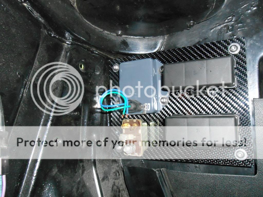
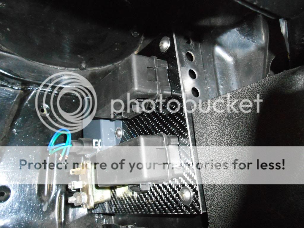
As you can tell I also removed the heater so all electronics are under the
dash where the heater box was.Brought the wire thru as low as I could just above the bell housing,


