For the ALT + I was gonna run it back all the way to the Battery side of the kill switch, (pre switch) so that when the switch is flipped it does not let the ALT to continue to provide power to the engine/fusebox. (necessary for tech inspection)JOE
I realize some guys do this but I don't believe this truely meets NHRA rules. The rules have a statement about "kills all power." Your method indeed kills the battery BUT it still leaves a nice big (no 8 or 6) welding cable "hot" all the way from the front to rear of the (wrecked) car.
A better way in my book is to buy a 4 terminal (2 pole) switch like Cole Hersey, like one of these:

Hook the main battery up through the big terminals as per usual. Ground either of the small ones, and run a no14 or so up front from the remaining small terminal. Hook this wire to one coil connection on either a relay large enough to run ignition loads, or a "continuous duty" solenoid, to switch same thing.
Hook your switch "Ignition run" coming from the ign. switch to the remaining small terminal of the solenoid or relay coil, and now you have a relay / solenoid which will drop out if either the key is switched off or the battery disconnect is pulled.
If you have a 3 wire alternator, hook one side of the relay/ solenoid to battery source, and ignition/ field/ regulator loads to the "cold side of the relay/ solenoid
If you have a 1 wire alternator, there are several ways to go but you DO need to use a solenoid, and not a relay. Hook the alternator charge wire to the battery side of the solenoid, and the ignition / other "run" loads to the switched post.
That way, if either the key is turned off or the disconnect pulled, the solenoid will drop, separating the alternator from the ignition, and of course the disconnect separates the battery.
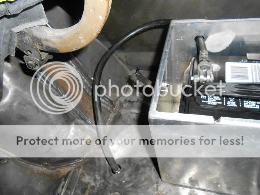
NO POWER anywhere except in the trunk.