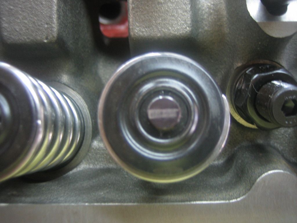
It looks a bit wide. How much valve lift are you running? The duration specs have no effect on how far the rocker moves.This is what the valve geometry looks like on my RHS heads. Sorta hefty springs, like 350 lbs + (.251/.259 @ .050" solid cam) 1.6 rockers.
You are using an out of date browser. It may not display this or other websites correctly.
You should upgrade or use an alternative browser.
You should upgrade or use an alternative browser.
Indy RHS head failure
- Thread starter V8-valiant
- Start date
-
I hear ya. I don't have access to Solidworks right now, or I would have some fantastic drawings for you. You definitely don't want me to do it freehand. You would really be confused. lolB3RE, I read your articles. Great stuff! A couple of drawings would make it a whole lot easier to penetrate, though. Especially for us foreigners.
rmchrgr
Skate And Destroy
It looks a bit wide. How much valve lift are you running? The duration specs have no effect on how far the rocker moves.
Really? I thought it looked dead nuts. Cam lift is .556/.549 x 1.6 = .593/.586
If the spring was in coil bind, something would have broken long before 1700 or so miles.please measure for coilbind
With that lift spec, the sweep should be less than .032" when properly set up. add in about .015" for a roller footprint, and the width of the stripe should measure less than .050". It looks wider than that to me. It is centered nicely, but that doesn't mean good geometry. It just means the rocker fulcrum length is long enough (actually too long) to put the roller on the center of the valve with the fulcrum being to low. When the fulcrum (shaft) height is correct, the roller on that rocker would be too far toward the exhaust side of the head because of the extra length. That means the shaft would need to be offset more than would be necessary if the rocker was the right length to begin with.Really? I thought it looked dead nuts. Cam lift is .556/.549 x 1.6 = .593/.586
nm9stheham
Well-Known Member
With the 1.6 ratio rockers, the actual lift would be more like .575 and .580.
If the failed valve and the about-to-fail valve are both intakes, then that gives a bit more credence to the idea of valve float. The intakes are heavier and would tend to float just a bit sooner than the exhausts. (Of course, the pushrod and lifter weight would be the same for both.)
If the failed valve and the about-to-fail valve are both intakes, then that gives a bit more credence to the idea of valve float. The intakes are heavier and would tend to float just a bit sooner than the exhausts. (Of course, the pushrod and lifter weight would be the same for both.)
I hear ya. I don't have access to Solidworks right now, or I would have some fantastic drawings for you. You definitely don't want me to do it freehand. You would really be confused. lol
Well, you never know. You'd be surprised by my drawing interpretation skills. I can sometimes tell what my 3-yo has tried to draw.
mopowers
Well-Known Member
This is what the valve geometry looks like on my RHS heads. Sorta hefty springs, like 350 lbs + (.251/.259 @ .050" solid cam) 1.6 rockers.
What rocker arms are you running?
rmchrgr
Skate And Destroy
With that lift spec, the sweep should be less than .032" when properly set up. add in about .015" for a roller footprint, and the width of the stripe should measure less than .050". It looks wider than that to me.
Where/how do you come up with that number? Just curious. Is it a percentage or is that number some sort of standard? If it is too wide it's not by much. I initially thought it was too narrow. There can't be that much wasted motion here if any.
It is centered nicely, but that doesn't mean good geometry. It just means the rocker fulcrum length is long enough (actually too long) to put the roller on the center of the valve with the fulcrum being to low.When the fulcrum (shaft) height is correct, the roller on that rocker would be too far toward the exhaust side of the head because of the extra length. That means the shaft would need to be offset more than would be necessary if the rocker was the right length to begin with.
That is true because when I did shim it, the pattern moved toward the exhaust side. I used an adjustable pushrod and dial indicator set up on the valve retainer to check for max. lift with the valve all the way open. I know got it right, I spent a lot of time with it.
So what to do? To get it perfect you'll be doing custom machining on every single part. If I wanted to get into that level of perfection, no way I would be running RHS heads, I'd be looking into much higher cost aluminum stuff. Sure, I could machine the rocker stands and make some offset blocks but that's where I draw the line, these are 'budget' heads and doing that sort of stuff throws budget out the window. I think it will run pretty good and won't be leaving much on the table with what I have.
Sorry to the OP for the hijack. Not sure if this pertains to your broken parts but I guess the question is whether or not you checked this stuff before hand and if the parts selected work together. I suppose a real bad geometry issue could cause what you have. I read the title thinking that head itself was the issue but that's not the case here.
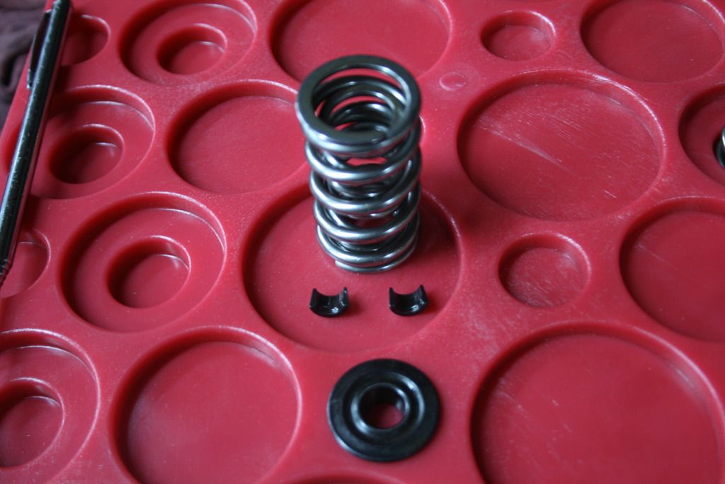
These are the springs, valve locks and retainers I have. Not sure what they are, they came with the heads. Probably not the best pic, sorry.
rmchrgr
Skate And Destroy
What rocker arms are you running?
Hughes.
moper
Well-Known Member
There's been more than a couple valvetrain failures posted lately. I don't think that's a lock issue. I think like Mike says it's a valve control issue. Broken parts break for reasons. Don;t be quick to assume it's a part failure, rather than a parts matching failure.
Can you post the spring part number, the installed height, and pushrod diamter and length info?
Can you post the spring part number, the installed height, and pushrod diamter and length info?
Dragonbat13
Well-Known Member
I want to say that I found this info elsewhere on the net, and I am not a super awesome engine builder. Heck I seem to just store engine parts for some odd reason.
But I have been looking into building a budget spring setup for some EQ heads.
I saw quite a few places where Comp keepers have been failing. Most recommended was crower keepers. ALSO, there was a statement where the +.050 keepers to add installed lift had the lock groove lower in the keeper, which is where there was less force applied if valve float occured. Now this is bench race stuff, but I would think those two things would be something to consider. Thats why I asked earlier. I cannot tell in the OP pictures because I dont know what the higher installed height keepers look like. But I am eyeing this thread closely to learn.
nm9stheham
Well-Known Member
The .032" number comes from working out the geometry. I actually worked it out last night for a 1.6 PRW rocker and for the most ideal rocker shaft height setting, it worked out to .034" of roller contact movement across the valve tip.Where/how do you come up with that number? Just curious. Is it a percentage or is that number some sort of standard? If it is too wide it's not by much. I initially thought it was too narrow. There can't be that much wasted motion here if any.
The scrub pattern above does not look all that wide; it scales to around .080" wide. But don't look at that pattern in the context of a standard stamped or 273 rocker, or even for other roller rocker brands. They will be considerably different, 'specially the stock types versus a roller type.
Having said that, I am not yet convinced that engines will always explode with something different than the 'most ideal' rocker shaft height setting for many or most engines. This whole theory has to do with the valve velocities varying too much and thus causing valve float. My initial results last night were that with .600" valve lift, and the shaft centerline too low by about .300" (a VERY extreme situation); the scrub width would be .130" wide the valve velocity varies no more than around 10%. (These number are for the PRW 1.6 rocker only so don't take it as a general result that applies to all rockers.)
That max velocity is at peak valve lift in that really bad case scenario, but all that gets tempered by the fact that the velocity is reaching zero at that point due the cam profile anyway. My bet is that this may be an issue when you get to extreme cases and highest lifts, up in the high .500's range, but not a worry at lifts at .500" and lower.
There's been more than a couple valvetrain failures posted lately. I don't think that's a lock issue. I think like Mike says it's a valve control issue. Broken parts break for reasons. Don;t be quick to assume it's a part failure, rather than a parts matching failure.
Can you post the spring part number, the installed height, and pushrod diamter and length info?
Still waiting to hear back from the business where I purchased them from, I will get all the details on springs, valves, and keepers and post it as soon as I know.
It is a mathematical equation that takes into account the radial sweep of the rocker when the fulcrum point is at the proper location.Where/how do you come up with that number? Just curious. Is it a percentage or is that number some sort of standard? If it is too wide it's not by much. I initially thought it was too narrow. There can't be that much wasted motion here if any.
If you set up for max lift you will most definitely be at the wrong place. Contrary to popular belief, proper geometry will actually lose a few thou at full lift.That is true because when I did shim it, the pattern moved toward the exhaust side. I used an adjustable pushrod and dial indicator set up on the valve retainer to check for max. lift with the valve all the way open. I know got it right, I spent a lot of time with it.
Hey, if you're happy with it, run it. BTW, it doesn't take custom maching on every part to get it right.So what to do? To get it perfect you'll be doing custom machining on every single part. If I wanted to get into that level of perfection, no way I would be running RHS heads, I'd be looking into much higher cost aluminum stuff. Sure, I could machine the rocker stands and make some offset blocks but that's where I draw the line, these are 'budget' heads and doing that sort of stuff throws budget out the window. I think it will run pretty good and won't be leaving much on the table with what I have.
The PRW has a shorter fulcrum length than the one I used for my calculation. Shorter fulcrum=more sweep.The .032" number comes from working out the geometry. I actually worked it out last night for a 1.6 PRW rocker and for the most ideal rocker shaft height setting, it worked out to .034" of roller contact movement across the valve tip.
Sorry, but I think a sweep pattern that is 200% wider than it should be is problematic.The scrub pattern above does not look all that wide; it scales to around .080" wide. But don't look at that pattern in the context of a standard stamped or 273 rocker, or even for other roller rocker brands. They will be considerably different, 'specially the stock types versus a roller type.
First, .300" is not unheard of. I've seen and corrected plenty that were off that much and more. Also, I believe you might want to recheck your work on the velocities. There should be no velocity at full lift when the geometry is correct because the valve stops and dwells, just like the piston does at TDC. Try to visualize what would happen if it was possible to have max piston speed at TDC.Having said that, I am not yet convinced that engines will always explode with something different than the 'most ideal' rocker shaft height setting for many or most engines. This whole theory has to do with the valve velocities varying too much and thus causing valve float. My initial results last night were that with .600" valve lift, and the shaft centerline too low by about .300" (a VERY extreme situation); the scrub width would be .130" wide the valve velocity varies no more than around 10%. (These number are for the PRW 1.6 rocker only so don't take it as a general result that applies to all rockers.)
Really, I had a .490" lift small block pick up 600 rpm on the dyno from correcting the geometry, and it was unstable 1000 rpm below peak. Also, the cam lobe dwells very little at TDC on a flat tappet, and the lobe velocities are multiplied by the rocker ratio. Try running full speed at a brick wall, and then just stop right at the wall, never mind trying to turn around and run back to where you started.That max velocity is at peak valve lift in that really bad case scenario, but all that gets tempered by the fact that the velocity is reaching zero at that point due the cam profile anyway. My bet is that this may be an issue when you get to extreme cases and highest lifts, up in the high .500's range, but not a worry at lifts at .500" and lower.
yellow rose
Overnight Sensation
Easy now, I didn't say they were stronger, I said they had more colleting effect on the valve stem. They won't unlock as quickly as a 10 degree lock will. They can pull through the retainer with high spring loads and valve float, but strength wise, the 10 degree has a heavier wall, which makes it stronger, all else being the same.
I get it, but the pull through issue is not a big a deal as most make it. To me, the collet effect is much more important.
That said, I usually use 10* stuff because it is more popular and easier to get. I have used 7* stuff with 350 plus on the seat and almost 1000 OTN and the 7's didn't fail.
So, I think like you. The OP has a geometry issue that is causing a harmonic or some other issue that caused the failure.
BTW...if this is the car I have seen it is a dang nice car, and I don't think the OP skimped anywhere. Just a little off on geometry has come back to bite him. You can tell from the posts in this thread that many have much to learn about shaft rocker geometry, if they would admit they don't know or understand.
cannucky
The Guy With No Birthday
Thanks for the plug on the tech articles, but nobody knows where to go. I can't post the link, but you can.O
PS. I should be writing a new article right now.
Sorry Mike but it probably doesn't work that way either , the same invisible hand that removed your link would step in and remove it from my post as well and I get in enough trouble on my own eh! LOL . Then again I don't know how to make a link so what the heck I'll just say it B3Racing Engines is the place to google for all this great info , both on the .com scene or FBook .
justinp61
Well-Known Member
- Joined
- May 15, 2009
- Messages
- 3,071
- Reaction score
- 4,059
tarvin890
tarvin890
Next time post a GRAPHIC IMAGES WARNING.....I nearly vomited when those pics came across my screen... how dare you!
p.s. sorry for the loss of your baby mopar...may i suggest a gofundme page to help you through this time of loss...
p.s. sorry for the loss of your baby mopar...may i suggest a gofundme page to help you through this time of loss...
hate this for op,but i wouldn't put my car in storage for a couple years....i'd find a cheap engine,stick it in there and keep cruisin.
Thanks, it's not all just loosing the motor. I'm making a carrier chance and wont have the "extra" funds for a while. Training for the new carrier starts first of the year and I don't plan to take any loans. Gotta save $14k for that and then between getting on my feet and going through a house change also, my play money has come to a hault for a while. I do have a motor out of my 68 d100 that it may get.... Sometime.
-


