I had a problem with my fuel gauge going all the way up when I turned the headlight switch on. It was recommended that I add a better ground to the instrument cluster. Today I removed the instrument cluster and verified all the screws on the back were tight. I then made a ground wire that a ran from one of the instrument cluster frame screws to the dash frame. It was clean and shiny, bare metal. It's affecting the temp and fuel gauge. I had them recored last year by instrument specialties as well as a new converted instrument voltage regulator. I called and the recommended checking the orientation of the cluster round plug to make sure the wires were in the correct order. I compared it to my 65 fsm wiring diagram and everything matches. It's frustrating because the whole dash harness and engine/light harness are all new replacements. I can't remember when they all worked right. It's a pretty simple harness, not much plugged in. It's only affecting the temp and fuel gauge when either the key is turned to power or engine is running. The fuel goes all the way full and the temp goes all the way high. Is there a way I can verify the problem? Could it be a defect in the ignition switch? The ignition switch is fairly new. It has an extra terminal on it that says ground. Where does the ignition switch get its ground? I took the switch out of the cluster and let it hang but had the chrome collar on it and everything worked the same. Does it get it's ground from the chrome collar?
You are using an out of date browser. It may not display this or other websites correctly.
You should upgrade or use an alternative browser.
You should upgrade or use an alternative browser.
65 Valiant now gauges go full when ignition key turned or running
- Thread starter wh23g3g
- Start date
-
nm9stheham
Well-Known Member
What do you mean by a "new converted instrument voltage regulator"? And do you have any more details about what the gauges were 'recored' with? We need to know what was put in your system, so we can see if it compatible with Mopar parts and your sensors. In looking at the Instrument Specialties site, the say that they recore with VDO cores, which are probably not at all compatible with your Mopar sensors. Mopar sensors are pretty low resistance compared to others.
» Gauges & Clusters Instrument Specialties
Do the following: Remove the wire from the temp sensor on the engine and measure the voltage there when the key is in RUN. It should be either 5v or a pulsed voltage (depending on the meaning of that new converted instrument voltage regulator). This will tell if the regulator is doing what it should for Mopar sensors.
Does the fuel gauge still go up when the headlights are turned on?
I think I actually got the instrument voltage regulator from RTE. I think it's converted to a solid state voltage limiter and it has the red led in it. You can't hardly see it anyway on the back of the dash so it doesn't really help me. I looked through my receipts and I believe the fuel gauge recored and the temp gauge recalibrated from Instrument Specialties. They told me they just repair it to function as it would originally. Mine is all original 65 Valiant gauges. The fuel gauge and temp gauge stay up whether the lights are on or not with the key to run or engine running. The fuel sending unit and gas tank were changed maybe 2 or 3 years ago. I did change the connection on the fuel tank sending unit to an eyelet terminal with a nut holding it on because the original push on type didn't stay connected very well. The temp switch is fairly new as well. I've had the car for like 4 years now. I've tried a couple different gauges and I don't know if any have ever worked right. There's got to be some way to make them work and stay working. It has a killer transmission leak at the parking cover so I'm not able to drive it to a shop. They also recored the speedometer and it works good. The ammeter I had was no good so they replaced it with an NOS one and it works good.
What do you mean by a "new converted instrument voltage regulator"? And do you have any more details about what the gauges were 'recored' with? We need to know what was put in your system, so we can see if it compatible with Mopar parts and your sensors. In looking at the Instrument Specialties site, the say that they recore with VDO cores, which are probably not at all compatible with your Mopar sensors. Mopar sensors are pretty low resistance compared to others.
» Gauges & Clusters Instrument Specialties
Do the following: Remove the wire from the temp sensor on the engine and measure the voltage there when the key is in RUN. It should be either 5v or a pulsed voltage (depending on the meaning of that new converted instrument voltage regulator). This will tell if the regulator is doing what it should for Mopar sensors.
Does the fuel gauge still go up when the headlights are turned on?
67Dart273
Well-Known Member
There's a number of possibilities. I would pull the cluster and get it working "bench tested" before reinstalling. Some of these comments are "in general" not specific to your cluster
1....IVR may not be grounded. They all have three electrical terminals, 12V in, ground, and gauge power out. Make certain this is so.
2....Original 3 terminal fuel gauge may still have the original IVR making connection, "screwing up the works." Have you seen the surgery indicated by some sites, including RTE?
RTE Limiter Faq - rte
3...the gauges may have suffered damage from the old IVR not working correctly
You need to review some of the threads on here regarding testing. Get some method of test resistors. Either a big wirewound pot, or a tank sender, or at least three test resistors. you can "set" the pot/ sender for the proper test resistances, or substitute individual resistors to obtain empty / mid / full readings on all three gauges
Here:
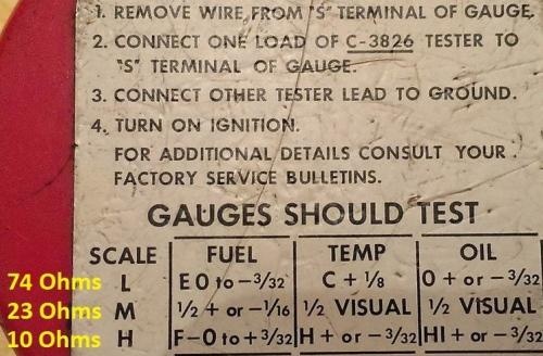
Hey Del, Look what I found!!! An original Miller Gauge tester!!!
This is right off the back of the Mopar test unit in the shop manual, the yellow values have been edited in. I did not make this photo
1....IVR may not be grounded. They all have three electrical terminals, 12V in, ground, and gauge power out. Make certain this is so.
2....Original 3 terminal fuel gauge may still have the original IVR making connection, "screwing up the works." Have you seen the surgery indicated by some sites, including RTE?
RTE Limiter Faq - rte
3...the gauges may have suffered damage from the old IVR not working correctly
You need to review some of the threads on here regarding testing. Get some method of test resistors. Either a big wirewound pot, or a tank sender, or at least three test resistors. you can "set" the pot/ sender for the proper test resistances, or substitute individual resistors to obtain empty / mid / full readings on all three gauges
Here:
Hey Del, Look what I found!!! An original Miller Gauge tester!!!
This is right off the back of the Mopar test unit in the shop manual, the yellow values have been edited in. I did not make this photo
nm9stheham
Well-Known Member
OK, well first test the voltage at the lead at the temp sensor as I described to check the RTE IVR. It is supposed to mimic the original IVR and should show you a pulsed voltage; your meter will show it jumping up and down.
Then test the gauges with some resistors like Del says above. They can be small resistors but they might get hot fast. I'd try one around 22 or 24 ohms connected to the end of the temp sensor wire to ground to see if the temp gauge went to near mid-scale.
Do you have a PN on the temp sensor? The new ones tend to be off from the originals. And take a resistance reading through the temp sensor with the engine warmed up (if you can with the trans leak) and let us know.
And BTW, this sensor uses a temp sensor, not a temp switch; those are distinctly different parts.
Full continuous 12 volts to those 2 gauges will fry them. First thing I would look at is how the regulator is connected and mounted. Your description suggests everything else is working properly.
And I agree that those LEDs that cant be seen are silly. That regulator should include wire length to mount it remotely / out where it can be seen. Flashing LEDs to accompany the pegged instruments ? Still silly.
And I agree that those LEDs that cant be seen are silly. That regulator should include wire length to mount it remotely / out where it can be seen. Flashing LEDs to accompany the pegged instruments ? Still silly.
I found my RTE voltage limiter along with another temp and fuel gauge in my garage today. So I looked at the limiter that I currently have on the instrument cluster installed in the car and it's the one Instrument Specialties converted to solid state. So I swapped out the limiter today with the RTE limiter I found and now the gauge don't go to full when I turn on the engine, they don't move at all. I tried to do the the 1965 Plymouth voltage limiter test by probing the temp sender wire while engine running and the test light didn't flash, it didn't even light up. So I called Instrument Specialties and they said it's not going to because it's solid state now. I did unplug the temp sender wire on the head and verified it did have power going to it. So I thought maybe now the temp gauge might be working so I started it and let it run until the radiator got hot to the touch. But the temp gauge didn't move at all. The fuel gauge didn't move at all either. I can imagine the fuel gauge sending unit being grounded bad because that ground strap isn't very good. I verified turning on the headlights and dimming the lights but the gauges didn't go to full. So at least I know that now. Maybe I have two more fried gauges after spending all that money getting them redone. I have two more spare gauges and I think they're bad too. All the instrument cluster lights work, the oil light works, signal, bright lights. So I think that means the ground is good on the cluster? When you say to run a dedicated ground from the cluster to the steering column, where does it mount on the instrument cluster? Does it mount on the screw that holds the metal cluster to the bezel or do I put it under one of the circuit board screws?
Full continuous 12 volts to those 2 gauges will fry them. First thing I would look at is how the regulator is connected and mounted. Your description suggests everything else is working properly.
And I agree that those LEDs that cant be seen are silly. That regulator should include wire length to mount it remotely / out where it can be seen. Flashing LEDs to accompany the pegged instruments ? Still silly.
nm9stheham
Well-Known Member
Please listen.. and I am not fussing at you. Unless you use a voltmeter and test as described, you are not going to be able to troubleshoot this. It'll just be a miracle if the right parts get in there. And you may indeed just go about blowing things up needlessly. We can get you through this, but you gotta help with doing things sensibly.
Do yourself a favor and go get an inexpensive voltmeter at a building store or auto parts store and start fresh. A meter will for sure pay for itself here, and it will be used more for charging system work and battery checking.
Do yourself a favor and go get an inexpensive voltmeter at a building store or auto parts store and start fresh. A meter will for sure pay for itself here, and it will be used more for charging system work and battery checking.
A dedicated ground should attach from inst' panel to chassis ( as in chassis ground ). Factory likely would have routed it to metal behind nearest kick panel. Find ample examples of this practice in your local parts yards.
You have probably read "attach to steering column" in this forum. Steering column is a separate part. So is the dash. Example scenario, you wish to pull the panel out a distance for in car testing. Lowering the steering column for this interrupts the ground you added. The word 'silly' comes to mind again.
Best place on the inst' panel to attach the ground... secure I this vibrating environment means ring terminal and toothed washer just like the factory used at ALT' gauge. The little sheet metal screws in circuit boards are not long enough or into enough material.
Pic of backside of your panel will help me help you.
I have my voltmeter today but didn't know what to test. I tested voltage at the temp switch and it's less than a volt. I've got the rte solid state regulator in and the voltage at the ign terminal is 11.65. My battery is at 12.40. I tried an original used regulator I had and probed the temp switch while engine running and it didn't even light up. With the original regulator non solid state it shows about the same voltage on the ign terminal. What should I try now?
I really just don't know what else to tell you. If a solid state regulator sends about 5 volts through a gauge and out to a sender, the bulb in a 12 volt test probe isn't going to verify voltage unless you're in a deep dark hole.
I'll back away gracefully. Other members who own 65 model and/or RTE regulator may not need pics, etc... can help you. Good luck with it.
I'll back away gracefully. Other members who own 65 model and/or RTE regulator may not need pics, etc... can help you. Good luck with it.
Last edited:
I'm about to give up on it. It's taking up too much of my time. I at least wanted to get the gauges working so I could drive it around the block every once and awhile. The car isn't worth sending to a shop to have it professionally diagnosed. I'm afraid I don't have the knowledge to test it but for what comes out of the manual and as long as I'm using the same tools in the manual. It's aggravating because the temp gauge worked fine before I sent it to be calibrated but the fuel gauge needed to be re-cored. I found two more extra gauges I have in a shipping box I have in the garage but don't know how to test them properly outside of the car.
nm9stheham
Well-Known Member
Sorry for the frustration..... Is the LED on the bottom (connector) side of the RTE limiter flashing when the key is in RUN? Is the case of the RTE limiter grounded to chassis, directly or through the clusters ground? Is the cluster properly grounded as you try these tests? The voltage at the IGN teminal is OK. And I am assuming this is the IVR 4 RTE model; is it?
How much voltage do you see with your meter at the end of the temp sensor wire with it disconnected from the sensor, with the RTE unit installed, and the key in RUN? Makes sure the case of the RTE limiter is grounded to the proper traces on the dash circuit board, and that the dash I may be jumping up and down. Do your best to describe the readings.
If you want to test the other gauges outside of the car:
1) Use a 12v battery as a power source.
1a) To check your power source and setup, connect the RTE limiter to the battery with the 12v going to the + terminal and the case of the limiter to the -. See if there is a pulsing voltage at the output terminal of the limiter and that the LED is blinking. Then disconnect the limiter for now and.....
2) Buy 3 resistors from www.mouser.com. All 3 should be 1 watt rated, and their resistance values are 10 ohms, 22 (or 24) ohms and 72 ohms. These will be used to create your own gauge tester.
3) When you get the resistors, connect the RTE limiter to the battery with the 12v going to the + terminal and the case of the limiter to the -.
4) Connect one terminal on the the spare temp gauge to the RTE limiter output and the other terminal to one end of the 10 ohm resistor. The connect the other end of the 10 ohm resistor to battery -. The gauge should slowly move to H (hot) or close to it.
5) Replace the 10 ohm resistor with the 22 ohm one and see if the gauge goes to about halfway.
6) Then connect in the 72 ohm resistor and the gauge shouldread C.
7) Repeat steps 4, 5, and 6 with the fuel gauge and see if it reads around F, 1/2, and E in that order.
If you were close to Waynesboro, VA, I'd lend a hand.
It is the IVR4 limiter. I cannot even see that led because it is so small and so up in the dash. The limiter is plugged into the gauge cluster board just as the original was. I was trying to make sure I didn't put it in backwards but it only goes in one way. So whatever way the way the factory intended on it being ground is the way it should be grounded. Whether it has a good ground or not I'm not sure. All the lights work on the cluster, so I'm assuming it's grounded ok. I put the ground lead of the voltmeter on the kick panel metal where there is usually some factory grounds when I was performing the test I did. I did test the temp sensor wire unplugged and it wasn't even reading a full volt with the RTE IVR4 plugged in. I don't know why that would happen. Maybe I didn't have the ground lead of the voltmeter grounded well, but I tried moving it to several spots to see if it changed. It may make sense to you'll here that when I put in a used original instrument voltage regulator that the gauges go full but when I remove it and put in the RTE IVR4 the gauges don't do anything. So it's just a matter of finding out where the problem is. How do I tell if the RTE IVR4 is properly grounded to the instrument cluster case? When the limiter is plugged in it's hard to test anything behind there. And if you have the cluster pulled out just a little to mess with it, you have to be careful because it's made to sorta wrap around the column tube and if you're not careful the plastic bezel could break at the corners. I can still get to the back with it installed easier than any other car I've got. It's just probing at it can be tricky. You don't know how many times I've had this cluster out. I tried to score an original gauge tester on EBAY but it went too high to make any sense of buying.
nm9stheham
Well-Known Member
OK, sounds like it SHOULD be installed right.
- The other limiter is suspected as kaput and is putting a full 12v to the gauges and so that is why they went full scale. Whether they are damaged or not now is the question (as I think you know).
- The output from the stock limiter and the RTE IVR4 is a pulsed 12 volts. It goes from 0 to 12 volts and then back to zero. It is 12 volts about 15-20% of the the time, and 0 volts the rest of the time. This is done to mimic the power available in a 5v system. This gauge design originated when car systems were 6 volt systems.) Your meter will register this pulsing differently depending on the meter. Do you have a digital meter, or one with a needle? If the meter reading wiggles up and down then it sounds OK; it is hard to tell with the way that every meter type responds differently to this pulsed voltage.
- The test described above with the resistors is what the gauge tester would do. Buy the resistors and some test wires with alligator clips to hook it up and go to town testing gauges. The whole deal will cost you a few bucks and you'll be an expert in no time. But you have to have a known good working limiter or a 5 volt source.
- Can you sneak a mirror up behind the panel and see the IVR4 LED light reflecting off of the circuit board?
- Otherwise, take the IVR4 out and use some test jumpers. Connect the 12v input to battery +, the ground to the battery -, and see if the LED is blinking. If not, then jumper the output to the temp sensor on the engine and look for the LED to blink. One thing I realized I can't remember 100% is where the 12v input is on the IVR4. I think it is the spade lug closest to the middle; looking at the RTE limiter FAQ's page confirms this. RTE Limiter Faq - rte
- If you can't figure out if the IVR4 is working or not, then use a 6 volt lantern battery, or set of 4 1.5volt batteries, as a temporary test source for in-car or out-of-car testing. The 6v battery would hook to the cluster where the tab on the IVR4 that is furtherest away from the ground tab connects. If you are hesitant, I would try this out-of-car with the spare gauges and resistors first.
- Sorry I don't have the time to diagram it out for you.
I'm going today at least try the gauge test today if I can find a radio shack still open. They're all out of business here. I found two more original voltage limiters off of two clusters I have for my 73 charger. Now I have 2 solid state limiters and 3 original limiters. Out of they all can't be bad. I will try the pulse test too but I have a digital voltmeter. I also found a spare 65 valiant circuit board which I've suspected all along but haven't tested. I think I'm going to swap the boards since it shouldn't take more than 30 minutes. I really hope I can locate the resistors today to test these gauges.
nm9stheham
Well-Known Member
With 5 limiters, I would hope 1 would be good! The RTE's and the originals behave the same way, with the pulsed 12 v output. Hard to see with any accuracy on a digital meter; the sample rates just does not match the pulse rate of the limiter. My Fluke meter shows over 10 volts on occasion, but misses most voltage pulses. An analog meter shows every pulse but not to full scale since it is too slow to respond. My old Tripplite shows every pulse but only to a peak of 6.5 volts on a 12v full scale setting; it is too slow to show the full pulse voltage.
The limiter on my original '62 pulses about 2x per second with the key set to RUN but the engine not running.
The limiter on my original '62 pulses about 2x per second with the key set to RUN but the engine not running.
I went to Radio Shack to get the resistors to test the gauges but they only had 1/2 watt and 10ohm and 22ohm. Will that still work? But today I thought I was done. I had everything working the way it should and I thought that was the end of it. I went over and tried one of the other two original instrument regulators that I borrowed from my spare 73 Charger panels. I put one in and turned the key and nothing happened. At that time I decided to pull the cluster out and take a closer look. After I got it out I noticed that when I unplugged the round bulkhead connector from the instrument cluster one of the pins was totally sheared broken. At that point I replaced the board with the spare 65 Valiant circuit board I brought with me and then I put back in the spare instrument voltage regulator then reinstalled the cluster. I turned the key and the fuel gauge went to 1/4 tank, right where it should be. So I started the engine and let it sit and idle for about 20-25 mins and the temp gauge slowly moved to the first tic. I don't know how accurate it is but it was right about where it should be for normal temp. I was happy. After that I figured everything was fine so I switched the regulator back to the RTE since everyone swears by it. Then I turned it on and nothing happened. No lights, no gauge movement. Then I swapped back to the original limiter. I turned the key and the fuel gauge went right back to 1/4 where it should be and the temp gauge moved a little. So then I decided to see what happens with the headlights on. I pulled the switch and everything quit. No dome lights, no gauge readings, nothing. I checked my battery it had 12.50 volts. But there was no power at the alternator stud or the starter relay stud. Something bad happened. I fried an ammeter or fusible link. I didn't see the fusible link burned in half. I checked to make sure the ammeter nuts were tight. There weren't hot or melted. I couldn't find power anywhere after this. I don't know what happened when I pulled the headlight switch. Everything just quit.
nm9stheham
Well-Known Member
Wow, what a saga. BUT PROGRESS. So the RTE is shot it sounds like, and you gauges are good. Good unit IMHO but they can fail/be blown. And the dash... goo to find that.
If the headlights do not work now, check for 12v at the big lug on the starter relay and then at the other end of the fusible link where it goes into the bulkhead connector. If you have a 65, then the other end of the link should screw connect to a solid terminal at the bulkhead and not go through a spade lug. Fusible link wire can get brittle under the insulation and blow, and you can't see it. You might find a 'floppy' spot in the wire or some distorted insulation to show the spot. If you have 12v after the link and to the lug on the bulkhead, then check on the inside. From there it goes to a welded splice buried in the harness, and then splits to the headlight switch, the ignition switch, and the fuse block IIRC.
Oh I just reread your post: no 12v at the big lug on the starter relay? Check and CLEAN both battery terminals, then the cable to the starter and then one to the relay, and then check the - led from battery to block, clean the connections on the block, and then the ground wire from the back of the head to the firewall; clean both of those connections.
You'll get there.
When I was doing all this mess. After it lost power after I turned on the headlight switch for the first time I was able to jiggle the negative battery cable around the terminal and hit a spot where I saw the dome light come on. I did my "re-test" by pulling the headlight switch on and the dome light went right back off. After that I could no longer find any "sweet spot" by wiggling the negative cable on the battery post. I'm going to try a new negative battery cable because I've been looking for an excuse to change this one because the terminal is so much fatter than the positive and it just doesn't look right. I don't think I've ever unbolted and looked at the ground wire from the firewall to the block. I think mine goes from the head to the blower motor nut. Where does the Slant Six negative cable bolt to for ground? I've got mine bolted to the bottom of the block right under where the power steering pump would be. I don't remember if I mentioned it but after all that happened I checked for power at the alternator stud, relay stud, and the ammeter studs inside and there was nothing. It's either lost ground or fusible link has gone but I don't know how. Because everything always powered up as soon as I connect the negative cable. There was no burning smell or smoke so that's good news. I'll check it all out again the next day I'm off.
nm9stheham
Well-Known Member
I would move the ground calbe from the back of the head off of the blower motor nut. There should be a tapped hole int he firewall just for that connection.
My /6 battery - is connected at the same area: lower front of the block.
My /6 battery - is connected at the same area: lower front of the block.
cudajim
cudajim
Sounds like you need some help, what's your location?
I'm in north Georgia. I think I tracked it down to bad ground battery cable. Tightened it really tight started it up and everything works as it should. I will need to get a different kind of negative cable. So hopefully I'm done with this.
-


