alternator/regulator wiring help

-

340kid

Well-Known Member
Joined
Mar 2, 2010
Messages
179
Reaction score
2
I need to wire in the alternator & regulalator on my sons 72 416 Duster,
just not sure if i need to do anything differently since the battery has been relocated to trunk area, I have the +BAT terminal of the alternator running back to the trunk area to the battery, the amp guage is gone and bypassed entirely, i have an 8 guage running from disconnect in trunk up to BAT post on starter relay and then another wire feeding the power to a universal 12 circuit painless box (with fusible link) i am still running the original bulkhead and stock ignition switch and forward engine harness. the only connections im using now are the brown & blue tied together to feed the mallory box (small red wire) and the yellow to the starter relay.

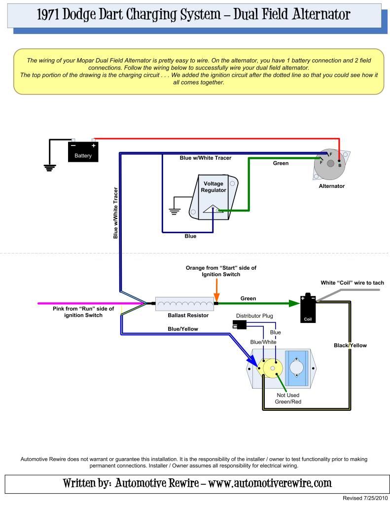
how should the 2 field terminals get wired in with the voltage regulator ?

thanks
340
 
Alternator field / regulator wiring should not change at all from factory.

However, I've said before, I do NOT like doing trunk systems this way, because you always still have a hot wire from the battery to the alternator. I don't believe this meets the letter of the NHRA rules, which somewhere has some comment about "Must kill all power."

If you guys would use a 4 terminal disconnect (that's 2 pole) you can use the small terminals to control a relay in the ignition/ alternator field circuit which will kill the motor, you'll only need one big battery cable + about a no14 for the other switch wire, and when the disconnect is pulled, EVERYTHING will be cold outside of the trunk.
 
i wired the voltage reg back in - green from VR to field term of altern, then blue from VR tied to brown & blue out of bulkhead which goes to ther field terminal ,
volt meter is showing no charge ???? does it matter which field terminals are attached to alternator ?? when key is put to the run position i have power at both terminals at the volt regulator connector. also when the key is on the voltmeter registers and shows draw, but with engine running it shows no charge ???
 
Make sure the VR is grounded. Scrape the firewall around the bolts, the back of the regulator case, use star washers

Check the alternator and field wiring by "full fielding" the alternator

The way these work is, the ignition switch (ignition run) feeds power to one field terminal (does not matter which one, you can switch field wires)

So power goes to one field terminal, THROUGH the field magnet, and back out on the GREEN

The regulator controls it by controlling the "amount of ground" so to speak on the green wire.

So get an 8?, or 10? - machine screw or some other probe that will make contact inside the regulator connector.

1---At the regulator connector, ground the GREEN terminal. Run the engine while monitoring battery voltage, say, at the starter relay or other battery "hot" point. Bringing up RPM should cause battery voltage to rise. If it does not, clip your meter to the alternator stud and try again. If it goes way up there, but not at the battery, your charging line is not actually continuous to the battery. If voltage does not go up at the alternator, but you DO have battery voltage (12.6) there----------------------go to 2

If the battery voltage DID go up in this test, check to be sure that the regulator harness connector and the regulator terminals are clean, and DOUBLE check that the regulator is grounded. Hook everything back up "normal" and recheck. If it does not charge, replace the regulator.

2--Might be a field wiring problem. Engine off, switch in "run", pull the green field wire off at the alternator, and clip that alternator terminal to ground. You should get a small spark. Measure voltage at the opposite field terminal to make sure you have battery voltage "under load." If you do, start the engine, and again check if charging voltage comes up. If not, you have problems with the alternator.

If voltage DOES come up, and did not in test 1, you have a field wiring problem somewhere

Basic diagram:

All you have is, the regulator "I" terminal (middle one) goes to switched 12 volts, along with ONE (either) field terminal. The remaining field terminal goes to the remaining terminal on the regulator, (F).

Dual_Field_Alternator_Wiring.jpg
 
i will try tests tomorrow, could be bad ground at voltage reg, will try this first
thanks
 
A few more comments. One reason I post as I do, is that you can easily be fooled by some measurements, example:

Especially on factory harnesses, ie "the bulkhead," a bad connection in the charging line path from the alternator, bulkhead, ammeter, back out to the battery, anywhere in there, can have a "good enough" connection, that if you measure the alternator stud / engine off, you'll "see" battery voltage.

But when charging, the bad connection will show up. This depends on how "bad" the connection "is." The battery may be running at a correct 13.8V, charging, but the alternator might be at 16, 25, 50 volts!!!!! So you MUST check this stuff under load.

So, "simplified," you need to check the alternator without the regulator, and OK or condemn the field wiring. But to check the alternator "stand alone," the basics are:

Ground either field terminal, and hook the remaining one to a known good battery source, like the start relay stud. This will "full field" the unit.

Then check battery voltage (at the battery or relay stud) while bringing up RPM, and compare that reading to the alternator output post. Depending on how "good" the charging wire / connection is, there should be less than 1 volt under very high output.

If you get stumped, confused, just post back, and we can take a different "angle."
 
i'm also having problems with this. i have an american autowire kit that is set up for a one wire alt, i have been persuaded to go with a stock alt with voltage regulator so i wire one in and without the battery hooked to the alt i'm showing 36v coming from the alt stud.
 
i'm also having problems with this. i have an american autowire kit that is set up for a one wire alt, i have been persuaded to go with a stock alt with voltage regulator so i wire one in and without the battery hooked to the alt i'm showing 36v coming from the alt stud.
NEVER run a car with the battery unhooked. The voltage can run upwards of 100 volts and/or send out spikes that will burn out every electrical component in the car.
 
The battery is still hooked up, it's the alt that I never hooked up. Is this normal? Will the alt put out that much voltage when charging?
 
The battery is still hooked up, it's the alt that I never hooked up. Is this normal? Will the alt put out that much voltage when charging?
Sorry, we had a communication breakdown. If the alternator is not connected to the battery, it can put out some high voltages. Connect the alternator to the battery, then check voltage output.
 
ok i hooked up alt and fired up car. i didnt get a chance to put a voltmeter on anything cause my volt guage in the car steadily climbed from 12v to 17v in about 30 seconds and was still climbing so i shut it down.
 
i'm also having problems with this. i have an american autowire kit that is set up for a one wire alt, i have been persuaded to go with a stock alt with voltage regulator so i wire one in and without the battery hooked to the alt i'm showing 36v coming from the alt stud.

How did ya wire it up?

Here is how I wired my dart using the AAW highway 22 kit. Never had any problem with it.


71DartChargingWiring.jpg
 
put extra grounds on i have 4 on just because and heavy wire its a 14 ft. pull from battery the rest follow the wiring diagram nothing but a hidden shut off should be differant hate to see it get stold or if racing some rules make you have 1 anyways on back of car
 
abodyjoe. i dont have a ballast resistor so to get the 12v ignition source i used the + side of the coil. from my understanding the blue wire needs to be tied into any power source so i used the coil cause it was the closest source. other than that it is the same as your drawing
winston. i have 3 grounds and the one from engine to firewall is directly to the one of the bolts for the voltage reg.
 
Fine to use coil+ if you don't have a ballast. That is straight from the key switch in "run" or "start" positions. Actually there is a slight difference that perceptive students might catch. That is that your alternator is then active while cranking the engine, so the starter has to work slightly harder. But seems that happens even with a ballast since it gets field current backward thru the ballast (from brn "start" wire) while cranking (slightly less than normal).

Most likely, you have excessive voltage drops in the wiring, so that the voltage sensed by the voltage regulator (blue wire above) is lower than what other components see. I recall that many other people have had this problem and it was due to drops thru the bulkhead connector, key switch, or wire harness.

One solution is to wire the Vreg sense direct to the alternator output stud, so it controls there (~13.4 V). One problem is that where you need the voltage in the cabin might then be much less. Another problem is that your Vreg would be active with the key off, so would drain your battery. To fix that, you need to have the IGN wire turn on a relay that passes the sense wire to Vreg. I vaguely recall that others have done that. I effectively do that since I installed a modern under-hood relay box in my A's, so my key switch now turns on the ignition relay and my Vreg controls the alternator output in the engine bay, so no drop thru the key switch. I don't worry about drops thru the bulkhead connector since my 65 has big dedicated studs. 63's had that too, but they dropped in my 64, brought back in 65, then dropped forever which caused un-told problems. If in your shoes, I would remove all the terminals in the bulkhead and clean them, since that will fix many of your problems. Also, feel for heat at the fused junction in the harness after the ALT wire (big black) enters the cabin. Those tend to corrode. I cleaned and soldered mine when re-working my dash harness.
 
-
Back
Top