Any electrical engineers or savvy guys? Need to design a circuit or something

-

DionR

Well-Known Member
Joined
May 7, 2008
Messages
6,796
Reaction score
3,947
Location
Spokane, WA
I have a project I am working on where I want to replicate the outputs of a new style switch but using an old switch. The new switch has a MUX setup where the resistance is varied based on switch position and uses 2 wires total while the old switch has different circuits for each position.

The ohms of resistances for the new switch I measured are as follows:

Off - 16.93K
Pos1 (Park) - 16.02K
Pos2 (On) - 15.55K

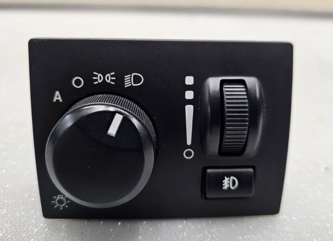
This is for a headlight switch out of a late model Charger. The old switch would be standard A-Body headlight switch.

Note that there is an additional complexity in that the Charger switch has a position for off that completes the circuit, rather than using an open circuit to indicate off. And just to be clear, this switch is only powered when the key is on.

Any ideas on how to wire up something like this? Maybe a circuit board or something?

Anyone have some knowledge about doing this kind of thing that they would share?

Thanks
 
What you're looking for is a comparator circuit - you use the switch as part of a voltage divider, and use two circuits to trigger relays at two set voltages, one for the parking lights and one for the headlights.
 
What you're looking for is a comparator circuit - you use the switch as part of a voltage divider, and use two circuits to trigger relays at two set voltages, one for the parking lights and one for the headlights.

Thanks, I will look it up.

But to be clear, I need 2 output voltages, not 2. Off needs a voltage output as well, that is less than the 5V input.
 
This must be a 2024-25? Here is some info about the circuitry. What a pain! Easier to fit a standard rotary switch with a few more wires/less Rube Goldberg. The earlier chargers had plenty of pins to connect but I don't know anything about the circuits/if they go to the ecu or directly to relays/lights.

Voltage Levels Control Relays Circuit Diagram
 
Sorry, had it backwards and thought you wanted to use the two wire switch for conventional headlights. The other way round just needs a resistor network. I'll need to do a bit of math for the details.
 
If only there were some kind of…like…a way how to build a circuit for park-tail-headlights on a car which (stay with me, this gets complex) doesn't involve voltage dividers or CAN or LIN buses. Like (just blue-sky spitballing here) maybe have a switch configured to make/break more than one circuit, depending on which of its three positions is selected. Maybe the switch could control a couple of relays to do the electrical "heavy lifting".

I know, I know: cuckoo-bananas; it's not possible. I mean, for one thing, that kind of a setup would be a nonstarter because then you wouldn't be able to require that a new replacement switch be paired with the vehicle, its battery, its left and right lights, and its driver's fingerprint and retinal scan in order to work.

But it's fun to dream.
 
This must be a 2024-25? Here is some info about the circuitry. What a pain! Easier to fit a standard rotary switch with a few more wires/less Rube Goldberg. The earlier chargers had plenty of pins to connect but I don't know anything about the circuits/if they go to the ecu or directly to relays/lights.

Voltage Levels Control Relays Circuit Diagram

This is an '06-10 switch.

s-l1600.webp


The switch has a 5 wire plug, with all the wires going to the IP or a ground.

1767907635904.png


I am currently only working with the MUX circuit which seems to input 5V to the switch which then outputs a variable voltage on the return wire. At some point I will probably need to look into the dimmer circuit but that's a problem for future me, if at all.

I am toying with the idea of sequestering the IP someplace under the dash and using it only for converting switch inputs into CAN network messages. In theory, this was looking easier than building a Arduino board that would take the inputs and put them on the network, but that could change. But I don't want to use the new switch so I am trying to find a way to feed the IP the right signals using the old switch.

The idea is that the IP would tell the TIPM to turn on (or off) the headlights, among other things. One of those "other things" is running power door locks using a factory fob.

Frankly, this is the easy part of the project. The turn signals and high/low messages come from the steering column module (SCCM) and use the CAN B network, which is a real pain in these cars as it uses a different chip and protocol than the CAN C network to communicate.

But right now I am trying to eat the elephant one bite at a time.

BTW, I should already be able to start the car using the Charger WIN without all of this. This uses the TIPM, which would also control the factory fans. I could stop there, but I want the headlight load off the switch and don't want to add more relays when the TIPM is already setup to do that. Thus another exercise in frustration.
 
If only there were some kind of…like…a way how to build a circuit for park-tail-headlights on a car which (stay with me, this gets complex) doesn't involve voltage dividers or CAN or LIN buses. Like (just blue-sky spitballing here) maybe have a switch configured to make/break more than one circuit, depending on which of its three positions is selected. Maybe the switch could control a couple of relays to do the electrical "heavy lifting".

I know, I know: cuckoo-bananas; it's not possible. I mean, for one thing, that kind of a setup would be a nonstarter because then you wouldn't be able to require that a new replacement switch be paired with the vehicle, its battery, its left and right lights, and its driver's fingerprint and retinal scan in order to work.

But it's fun to dream.

Yeah, definitely more complex. But in the end, it's still driving relays for the headlights, doesn't require DNA or a background check to make work and adds functions like lane change and dropping a headlight when the turn signal is on (maybe). Either way, if I have this big ugly box in the engine compartment already that can run the headlights, why clutter things up even more with extra relays screwed to the inner fender with deck screws.
 
I might add that by keeping the IP, I think I can get the factory push to start function working by adding the PEM and the two RF antennas.
 
Coming from a microcontroller background, I'm thinking a software solution with a processor. The processor would have an Analog-to-Digital-Converter (ADC) that looks at the analog input and delivers to the software a 0-255 (8-bit), 0-1023 (10-bit) or 0-4095 12-bit) output. Thresholds are programmed so that the different voltages can implement different outputs. There is just nowhere near enough room in a post to educate you, but look into Microchip 8-bit processors (MPLABX IDE [https://www.microchip.com/en-us/tools-resources/develop/mplab-x-ide] with XC8 Compiler [https://www.microchip.com/en-us/tools-resources/develop/mplab-xc-compilers/xc8]) or even PICAXE (Home - PICAXE) offerings. Do the search. This stuff isn't for everyone, but if you're adventurous, OH MY GOSH what you can do!! It's like the 3d printing thing, but for controlling "stuff".
 
Coming from a microcontroller background, I'm thinking a software solution with a processor. The processor would have an Analog-to-Digital-Converter (ADC) that looks at the analog input and delivers to the software a 0-255 (8-bit), 0-1023 (10-bit) or 0-4095 12-bit) output. Thresholds are programmed so that the different voltages can implement different outputs. There is just nowhere near enough room in a post to educate you, but look into Microchip 8-bit processors (MPLABX IDE [https://www.microchip.com/en-us/tools-resources/develop/mplab-x-ide] with XC8 Compiler [https://www.microchip.com/en-us/tools-resources/develop/mplab-xc-compilers/xc8]) or even PICAXE (Home - PICAXE) offerings. Do the search. This stuff isn't for everyone, but if you're adventurous, OH MY GOSH what you can do!! It's like the 3d printing thing, but for controlling "stuff".

Just to be clear, you are suggesting I look into this so can tout the voltages I need to feed the IP, right? Not something to control the headlights itself?

I will look into what you have suggested either way. Thanks!
 
i Cheated on my road runner opened up the switch cut a few tracks & used Kynar wire to run the contacts directly to the terminals then used solid state relays to switch the lights position 1. Park & side runners,2 & 3 headlights if i push the button it flashes the headlights
I don't need dimmer with the Digital dash

light switch.jpg
 
Can you confirm the switch you want to use has three terminals, and turns on the Park terminal when the main lights terminal is on? If so, I can get you what you need with three resistors.
 
Can you confirm the switch you want to use has three terminals, and turns on the Park terminal when the main lights terminal is on? If so, I can get you what you need with three resistors.

It has 3 positions, is that what you mean by terminals? There are only 2 wires so it's not like the old switch where park is a separate circuit from headlights and stays on when the lights are on.
 
i Cheated on my road runner opened up the switch cut a few tracks & used Kynar wire to run the contacts directly to the terminals then used solid state relays to switch the lights position 1. Park & side runners,2 & 3 headlights if i push the button it flashes the headlights
I don't need dimmer with the Digital dash

View attachment 1716497136

So you are using the switch to control the stock headlights?

I expect I will be cracking one open at some point, but I would need to get another just in case I destroy this one getting it open.
 
I was asking about the switch you plan to replace it with. Does it have three separate connections for 12v, parking lights, and headlights, or are there more, like two separate 12v inputs, one for parking lights and one for headlights?
 
I was asking about the switch you plan to replace it with. Does it have three separate connections for 12v, parking lights, and headlights, or are there more, like two separate 12v inputs, one for parking lights and one for headlights?

Ah, gotcha. Sorry about that.

Interesting. Looks like it has there are two 12v inputs, one for parking lights and another for headlights.

1767973717772.png


B1 and B2 are both 12v in. M is headlights (might be an H?) and R is parking lights.

I always assumed it had one 12v in. Guess not.
 
Ok, will you be using the dimmer on that switch for anything? That could complicate matters.
 
Ok, will you be using the dimmer on that switch for anything? That could complicate matters.

Going to get complicated to do the dash lights, but I can find a work around so I don't need it.

But the dimmer is hot in both park and on, so not sure how it works for this circuit. Unless I cut the connection between the positions?
 
adds functions like lane change

Now we're talking turn signals, not headlamps – and one-touch three-flash was a thing before the current craziness in vehicle electrical architecture.

and dropping a headlight when the turn signal is on (maybe).

Headlight: never.

Daytime running light: sometimes. And this, too, is easy without "operate the switch to send an encoded message to beg the BCM's permission to have headlamps, and await its decision" idiocy.

Either way, if I have this big ugly box in the engine compartment already that can run the headlights, why clutter things up even more with extra relays screwed to the inner fender with deck screws.

You're missing the point of what I posted; I wasn't advocating both-and, it was more of an either/or. But I will freely admit it was not really responsive to your question. I'm just bіtching in an old-man-yells-at-cloud kind of way.
 

Just to be clear, you are suggesting I look into this so can tout the voltages I need to feed the IP, right? Not something to control the headlights itself?

I will look into what you have suggested either way. Thanks!
The processor would activate MOSFETs that would activate either the actual load or a relay. You now have the ability to use logic and programmable thresholds for control.
 
Ok, I think you want to use your cars original headlight switch to replace the 06-10 switch. The dimmer is not an issue as it works the same way. Check the ohms across pins 5 and 4 at each end of the adjustment. It should just be a potentiometer like the original dimmer.

The other four selections (off,park,head,auto,fog) all output on pin 3. The internal FOG circuit is in parallel to the rotary switch circuit and reduces the resistance in each position so you actually have six different ohms values depending on what positions are selected.

FOG: For FOG, you need an off-on switch and resistor. Using the value of any position with and without FOG to determine what the value of FOG is using the resistance in parallel formula. With FOG off, you know the rotary ohm values already.

OFF: The original switch probably doesn't have any contact made pushed in/off so you'd need a jumper with a resistor to provide power to the cluster when running that can be in/on the cluster and nowhere near the original switch. The ohms value is not lowest in the OFF position so the other positions will be parallel paths to the cluster to reduce the ohms as needed for the position. The lowest ohms will be in HEAD, then PARK, then OFF, with the highest in AUTO. Need another on-off switch for AUTO that is powered only when the original switch is off. This can be done with a 5 pin relay.
 
Last edited:
Now we're talking turn signals, not headlamps – and one-touch three-flash was a thing before the current craziness in vehicle electrical architecture.

Yeah, it's kind of an all or nothing. Just focused on the headlight switch right now, you know...because of the elephant thing...

Headlight: never.

Daytime running light: sometimes. And this, too, is easy without "operate the switch to send an encoded message to beg the BCM's permission to have headlamps, and await its decision" idiocy.

Could be, I thought I have seen cars drop the headlight but maybe it was DRL's. I'm not even sure a 2010 Challenger has the function built in. Note that I said Challenger since those are single headlights like my Duster, not the dual headlights like a Charger/300. And yes, I have already been able to reprogram my TIPM to run single headlights.

To be completely clear, I am not doing this because I decided I wanted to control my headlights like a new car does, it is only one part of the project. I started down this road when I realized that a TIPM is prewired for almost everything I need to run my G3 swap, so I started looking into it for that reason. Later on, I realized that it was also doing the headlights, turn signals, brake lights, etc. So I started looking into using it to do all that as well since I would already have it in the car and (like I said above) I don't want loose relays someplace.

So it is an outgrowth of other projects, not a new project all on it's own.

You're missing the point of what I posted; I wasn't advocating both-and, it was more of an either/or. But I will freely admit it was not really responsive to your question. I'm just bіtching in an old-man-yells-at-cloud kind of way.

I didn't miss it, no worries. :D
 
-
Back
Top Bottom