charging problem

-
The first test was with the engine OFF

Thanks to both of you for the explanations. The fog is lifting.
 
"Second test" is OK

'=================================================
"First test" is AFU. I don't know what you did there

The "switched ignition comes FROM the key, THROUGH the bulkhead

After the bulkhead, it branches off to several places, so at least three should be "the same"

Those are

the 'key' side of the ballast

the blue field wire on the alternator

and the VR "I" or IGN terminal

So you need to hook one probe to any of those points, whatever you can "get to."

The other probe needs to go to battery POSitive

The key must be in "run" with the engine "stopped."

What you SHOULD read is very very low voltage

If you somehow read that 11.58 to ground, "it might be" that you accidently did the test in a different way

If you turn the key to "run"

Measure battery terminal voltage (to ground) and note it

Then move your "hot" meter probe to "switched ignition"

So let's say the battery read 12.6, and let's say your "switched ignition" read 11.58

You subtract those two, 12.6 -- 11.58 = 1.02 volts DROP!!!!!

If you had properly done the first test, this 1.02 is what the meter would read

What does this mean? It means the VR "sense" (the "I" terminal) "sees" 1.02 volts less than battery

IF the VR is properly attempting to regulate (it's set point) at 14V, then 14 + 1.02 means the battery will be running "at the battery terminals" at 15.02 volts

Depending on where in the circuit the bad connection is, this condition might get worse depending on what is turned on, headlights, etc.
 
One important thing for all of you getting used to using voltmeters and that will help in these troubleshooting threads: there is a + and a - on the voltmeter. The red lead is standardized as the + lead and the black lead, which should plug into the COM (common) terminal on the voltmeter is the -.


When making voltage readings, it will always be standard to put the - lead (black) of the meter to the battery - terminal or to ground, and use the red lead to measure the point of interest in the circuit. It is helpful to report whare you put the black (-)VM lead and where you put the red (+) VM lead.


And report if your meter reading is +x.yy volts or -x.yy volts. It can help those helpiing you to see if you are doing something wrong or perhaps help catch an odd circuit behavior.


Seems like a good sticky would be "How to correctly use a voltmeter to test your Mopar"....
 
The first test I had the red lead from the meter stabbed into the battery positive post and the black lead (plugged into the common terminal on the meter) on the dark blue field terminal on the alternator and then on the single dark blue terminal of the ballast resister. According to my wiring diagram these both go to the IGN terminal in the VR. The ignition switch was in the run position with the engine off. I did it a couple times. This seems to signify something substantially wrong somewhere if I should be getting a very low voltage reading at both those positions as you have stated. I followed the instructions very carefully and I'm getting +12.6 volts at the alternator dark blue wire and +11.58 volts at the ballast resister single dark blue wire side. Do I need to start unwrapping the loom and look for insulation problems? I can also always try another VR in case the new one is bad or a battery but I'd prefer not to throw parts at it if we can determine what the actual problem is through additional tests.

Thanks again to everyone.
 
If you did this as you describe, I would agree. Always "double check"

With the key in run, now use the meter "conventionally"

Ground one probe

Check at the ballast and compare that voltage to the blue field wire

Let's be clear..........you ARE on the blue "quick connect" field wire, and

NOT>........

the alternator stud.......(large wire)

or the green field wire ( second quick connect)
 
Correct. It's the dark blue wire next to the large plastic shielded wire on the stud. The green field wire is on the far outside.

I think we are narrowing this down. Doing as you said I first connected the meter's red lead to the blue field wire on the alternator (using a jumper with alligator clips) and touched the meter's black lead to the battery negative post. With the ignition switch on "run" and the engine off I got a reading of zero volts.

View attachment alt.jpg

Next I connected the meter's red lead to the dark blue single wire on the ballast resistor and the black lead from the meter to the negative battery post and with the ignition switch to run with the engine off, I got a reading of +11.35 volts.

View attachment br.jpg

From my factory manual wiring diagram I know that those two wires both come out of the same splice labeled as "NUMBER ONE SPLICE" so it seems to me that i should have the same reading from both? Do I either have a bad splice or a broken wire?

View attachment diagram.jpg
 
You have two problems. The reading at the ballast is low, indicating a voltage drop

But zero at the blue indicates a break. That wire "looks" like it's not factory

I would start right there at the alternator---the wire terminal on that blue wire.
 
It got painted by accident so it's a little lighter than it was originally and it does have a new end on it from a couple years ago.

Alrighty, I have some work to do checking this out. I work 12 hour shifts beginning tomorrow at 5am through Wednesday so it may be a few days until I can sort this out but I will report what I find....likely with more questions. Thanks much!
 
So while I work through this and get a better understanding of the charging system, is there any possibilty that the alternator itself is part of the problem? Is there a componant of the alternator which can fail so that even though the VR is correctly telling it to reduce the voltage output, the alternator doesn't listen and puts out all the voltage it can muster?

Currently the voltage in my Dart follows the engine RPMs once it gets a little above idle.
 
I would expect there to be no voltage at all going ground to ground.

I'll answer this one question since you have plenty of good help here. Ideally there is a very low voltage drop, but always some since the alternator field current (Ifield) flows to the Vreg case, then to the car body, then BATT-. Any resistance (R) in those can cause a voltage drop: dV = Ifield * R (Ohm's law). The biggest R in that path is the often rusty sheet-metal screws that bolt Vreg down. Not bad to run a dedicated jumper wire from the Vreg case to body gnd.

Vreg monitors only the voltage difference (dV) between IGN1 and its case. IGN1 comes from the key switch, after the bulkhead connector, at upstream side of ballast. Vreg tries to maintain dV at its internal setpoint (~14 V). If dV is lower, it increases the field current proportionally, and vice-versa. It should reach a stable control point near the setpoint. For more theory, read up on "proportional control loop" (wikipedia, etc).

Otherwise, I'll defer to winstoninwisc's short and elegant sentence.
 
It got painted by accident so it's a little lighter than it was originally and it does have a new end on it from a couple years ago.

Alrighty, I have some work to do checking this out. I work 12 hour shifts beginning tomorrow at 5am through Wednesday so it may be a few days until I can sort this out but I will report what I find....likely with more questions. Thanks much!

It occurs to me.............................

Pull both field wires off

Set your meter on "ohms" and check resistance across the two field terminals.

Then put one probe to ground, and check to each field terminal.
 
OK- My 12 hour day turned into a 14. Now it's past my bedtime. I'll check that tomorrow evening.
 
OK just as or far more important, is the resistance from each to ground? Should be infinity or "open" on both, so you need to make that test and post the results

==========================================

But that reading you posted is not accurate. The 20K meter scale setting means the meter can read "up to" 20K ohms, which is a fairly high resistance. Many (most) meters in "manual" mode won't give you accurate LOW readings on that high a scale. For resistance, you need to pick the LOWEST scale which gives you a "good" reading.

Check that again on the 200 range.

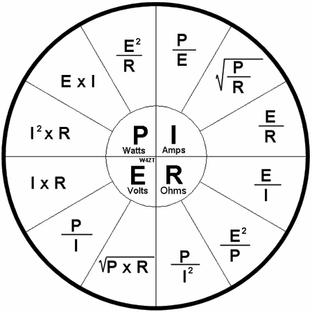
The field draws somewhere between 3 and 6 amps depending. So if you plug 3 and 6 amps into Ohm's law

Pie chart:
http://fixitnow.com/wp-content/uploads/2009/03/ohmspie-450x450.gif

You want to estimate R and we have some idea of what "I" (current in amps) is, and we have some idea what "E" (voltage) is so we use

R = E / I

or Resistance equals Voltage divided by Amps

So we solve for both 3 and for 6 amps to give us an estimate and we'll use 12V, nominal

12/ 3 is 4 ohms, 12 / 6 is 2 ohms

So the expected reading on your test is between 2 and 4 ohms.
 
OK I'll check again tonight with the meter set on the 200 range.

When I tested each post to ground, I ran through the entire scale on the dial from 200m to 200 and it was open for every one.
 
OK I'll check again tonight with the meter set on the 200 range.

When I tested each post to ground, I ran through the entire scale on the dial from 200m to 200 and it was open for every one.

That is good. I was afraid that the field was grounded, which might explain part of the problem
 
OK. Getting a start of my four day weekend here after taking care of some morning business.

I borrowed another meter to have a comparison. It has auto ranging.

I rechecked the two field terminals to ground and they are open. (with the green and blue field wires disconnected)

I rechecked the two fields to each other (with the green and blue field wires disconnected) and got the results below. As you see, the old meter is set on the 200 scale.

View attachment DSCN1023.JPG

View attachment DSCN1026.JPG

What do these numbers tell you?

I did find a problem with the bulkhead connector wiring. As I was having a peek around The spade from cavity "N" flopped out lose. This of course being the wire that runs to the "NUMBER ONE SPLICE" and to the VR Ign terminal, the dark blue field wire to the alternator and to the ballast resistor. Hmmmm...Seems we've been focusing on that circuit a bit.

Get that secured and plugged back in and see?

That right there is probably the trouble.

The test "to ground" on the field is good. You want them "open."

The 18--19 ohms is high, but we can deal with that "in a minute." This might indicate that the brushes are dirty, worn, or just "in a high spot." This at least shows some continuity

I'd concentrate on what you found at that bulkhead terminal...................
 
Well....cleaned up all terminals, reset the spade into the bulkhead connector plug (had to slightly pull out the locking tang so it would lock into the connector) and fired her up.

Max voltage at high engine speed-

View attachment DSCN1027.JPG

Holding quite steady throughout the entire range of RPMs. All the loom is neatly re-wrapped again with correct loom wrap. Looking pretty and running even better.

Can't thank everyone enough, especially 67Dart273. PM me your address and I'll send you a Starbucks card or something. This is obviously huge getting this fixed and I have a much better understanding of the system.

Thanks again-
Rob
 
No problem. No payment needed. Your thanks and getting it running is gratifying enough
 
Great thread, learned a lot about how the voltage regulation works in these old cars plus a thing or two about multimeters I didn't know. Definitely "Sticky" material.
 
-
Back
Top