Gauges and cluster light only work with lights on?!

-
So perhaps I've found the issue....let me recap just for my own thought process...the fuel gauge stud was reading 4.21v (below) where all other studs and copper were reading 5v. Metered the blue wire at the (newly soldered) pin on the cluster, still got 4.21v. Traced it back to the kick panel connector, 4.21v. Unhooked the connector and metered the male pin, 5.0v! Metered back up to the fuel gauge stud and pin, 5v!
 

Attachments

  • image.jpg
    104.8 KB · Views: 66
All you have done is this.......

When you broke the kick panel connector you REMOVED the load on the supply, the VR, and the gauge

This would be "what I'd expect" for a normal circuit, or at least "in reason."

I'm getting lost. I haven't seen where you have separated the sender circuit from the gauge

The 4 ....some volts seems to indicate that the sender is drawing "some" current as it should

Maybe take a different approach.

Separate the cluster harness connector, with the sender wire hooked up "as normal" up to the harness connector. Take an ohm reading from the sender wire to ground. Depending on what you read should be what you'd expect to read on the gauge, IE 10--15 or so, around full

25 ohms or so..........around 1/2 tank

60-75 would read empty

The fact that grounding the gauge makes it peg, and yet having the sender hooked up causes "what?" for a reading could be


1.....bad wire connections which you may have eliminated

2...."Sticky" gauge unit

3...Without measuring the sender, who knows what you are getting? to operate the gauge.
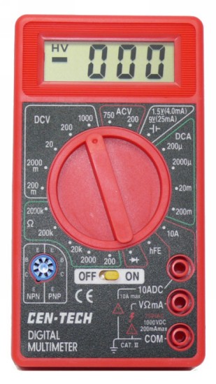
So.....i removed the blue sender wire at the tank and grounded it to a better piece of metal. Guess what, the needle pegged. Connected the wire back to the sending unit, ran a ground wire from the sender to good metal, no movement on the needle. After all of that, is it just a bad sender? (If it is then at least I learned a hell of a lot! And sorry to put you through all that.)
 
Mmmmmm, I see the measurement problem in pix #1 above......You are not using your meter correctly. The probes are in the wrong holes in the meter. The black goes into the bottom one and the red goes into the middle one; that arrangement is for mearuring both voltage and resistance.

Reading the voltage on these lines with a digital multimeter can be tricky and hard to interpret as different meters reacts differently to the pulsing voltage from the instrument voltage limiter.

So, you are better off making the sender resistance measurements with the wire from the guage removed as 67Dart273 suggests; that should give you stable readings right at the sender. The guage pegging with the wire grounded and then reading nothing with it conencted and the sender well grounded deso indeed indicate a bad sender. When you make the reistance measurements, put the red lead on the sender terminal, and then the black lead directly on the sender ring.
 
Well that makes sense. Almost sounds like you're not getting a good connection from the guage wire at the tank, or from the ground wire to the sender or to the body. Or the wire is broken inside the insulation where you can't see if and is making erratic connection. You are so close!

And now that I see you have a linear regulator, you sure OUGHT to be able to measure 5V at the end of the wire when disconnected from the sender. Try it again (with the meter leads plugged in the right holes, of course).
 
Found something interesting when i tested the sender.....oh btw I yanked the sender to test it outside of the tank. Just easier for me to literally visualize everything. Based on the bench tests, sender should be fine.

Here it is on "empty".
 

Attachments

  • image.jpg
    32.3 KB · Views: 54
Even at the full mark, it showed about 15ohms.....but when i hooked it back up to the sending wire and turned on the battery, even if the float was at the "half way" mark........
 

Attachments

  • image.jpg
    30.7 KB · Views: 45
Now when the float was moved to the "full" setting.....gauge went to ALMOST full. Doesn't go any further.
 

Attachments

  • image.jpg
    70.7 KB · Views: 49
Lastly, i ran a new wire from the kick panel connector directly to the sender (thinking that maybe the actual connector was faulty) as nm9stheham and 67dart273 previously suggested. Exactly the same results. Its as if the sender only starts working after the half way point. But bench tests show otherwise.
 
Well, it does not read as low as it should with the tank full....so that is why the guage does not go to full. Sender is not right with 34 ohms at the FULL positions. I'll give you kudos for a TON of persistence.
 
Well 34ohms was at the half way mark. At the full mark it read about 15. Oh and I re-measured with the meter prepped correctly. Everything read at 5v. Think I will just get a new sender and see what happens.
 
Here's what I'd do now that you have the sender out

1....Adjust the sender to about 23--25 ohms with your meter. Use the ohms "200" setting or whatever the "low" setting is on that meter. Tape, wire or otherwise "fix" the sender so it won't move.

2...Clip the sender with test clip leads right to the cluster ground, and right to the gauge sender stud. Turn on the power and see what it reads.

3...If it does not read 1/2 scale, measure voltage UNDER THIS CONDITION above from the gauge "power" stud to ground. You should see your 5V regulator voltage at that point.

I'm still thinking you have a poor ground or a bad connection in the sender wire, or the circuit path from the harness through the pins to the gauge connection, etc etc
 
You want to be using the bottom two probe sockets, and you want the knob pointing to "200" near the bottom, right next to the off-on switch

DVM1-L.JPG


(Our instructors in U.S. Navy "A" school, circa 1968, Treasure Island, used to say, "make sure the oh en -- oh eff eff switch is in the oh en position" LMAO)
 
Well 34ohms was at the half way mark. At the full mark it read about 15. Oh and I re-measured with the meter prepped correctly. Everything read at 5v. Think I will just get a new sender and see what happens.
OK, the posts were confusing; it looked like 34 ohms was the 'full tank' resistance. 15 ohms for full is not far off. I would not get a new sender at this point.
 
OK, the posts were confusing; it looked like 34 ohms was the 'full tank' resistance. 15 ohms for full is not far off. I would not get a new sender at this point.

It is.Gauge shown is proper response to 15 ohms.
80 ohms is no needle movement
10 ohms is allowable limit without damaging the gauge.
Your calculator would show the center of that range to be 35 ohms But...
That's not how it works. As the winding inside the gauge heats it's resistance changes.
The actual center of range is 23 ohms. From there on every ohm makes more difference in needle position. So the difference between 80 and 75 is less than the difference between 15 and 10. I hope this makes some sense.
 
Here's what I'd do now that you have the sender out

1....Adjust the sender to about 23--25 ohms with your meter. Use the ohms "200" setting or whatever the "low" setting is on that meter. Tape, wire or otherwise "fix" the sender so it won't move.

2...Clip the sender with test clip leads right to the cluster ground, and right to the gauge sender stud. Turn on the power and see what it reads.

3...If it does not read 1/2 scale, measure voltage UNDER THIS CONDITION above from the gauge "power" stud to ground. You should see your 5V regulator voltage at that point.

I'm still thinking you have a poor ground or a bad connection in the sender wire, or the circuit path from the harness through the pins to the gauge connection, etc etc

Ran the test exactly as you specified. Sender was at half way point (next to me on the floorboard) ran clips from sender to gauge stud and ground from sender to cluster ground bolt. No movement on needle. Measured at stud and ground screw, now reading 4v. Moved sender to full position, needle went to almost full. Measured at same points, reads at 1.9v.
 
-
Back
Top