Help stranded no power!

-

wheelman21

Mopar noob
Joined
Jan 1, 2011
Messages
208
Reaction score
0
Location
Bing NY
Ok so I drove my 73 dart sport to the shop for an inspection. I got it here, went to start it and I have no power. I have 12v at the battery and firewall. I also have power on the other side of the connector in the cabin. But when I turn the key I have nothing. No lights or radio or ignition. Where do I look?! Thanks guys.
 
If you have 12v at the firewall and anywhere inside, the fusible link is OK.
Clean both battery terminals.
Sending you a PM so you can call on the phone for help if so inclined.
 
fuseable link prob bad...remember you can have 12V but NO AMPS [so nothing will work] due to a tiny connection at the burned link.. double ck it..
 
Are you checking "inside the cabin" with a load turned on? EG: Let's say the problem is right there in the bulkhead connector. If "everything" is shut off and you show 12V, the connector might be "making" good enough to operate the meter. Do your testing with the key in ACC and the heater or other ACC, radio turned on. This places a load on the connectors

Did you check at the ignition switch connector where it enters the column?

Does ANYTHING "that is live" work? Stoplights? Headlights?

If "nothing live" works then this almost HAS to be.............

fuse link

bulkhead connector the red wire feed

ammeter connections or the ammeter itself

bad "welded splice" in the black ammeter wire


HOW TO GET HOME

If you have no brake lights, but can get someone to follow you and act as a guard so to speak, just hot wire direct from starter relay terminal to either ignition (MSD) or the "key" side of the ballast so you don't burn up the coil. Jumper the relay and it should run.

NOTICE!!! If you look at the 73 service manual, page 8-154, which shows the alternator / starter relay / ammeter wiring, it is CONFUSING AS 'ELL

Look up in the far top left corner at the alternator. It says "with 60A alternator" and "without 60 A alternator" This diagram shows BOTH wiring schemes, and shows the grommet in the firewall for ammeter wiring. THIS IS ONLY USED on the optional 60 alternator. All others use the same old "bulkhead connector" feed through.
 
Are you checking "inside the cabin" with a load turned on? EG: Let's say the problem is right there in the bulkhead connector. If "everything" is shut off and you show 12V, the connector might be "making" good enough to operate the meter. Do your testing with the key in ACC and the heater or other ACC, radio turned on. This places a load on the connectors

Did you check at the ignition switch connector where it enters the column?

Does ANYTHING "that is live" work? Stoplights? Headlights?

If "nothing live" works then this almost HAS to be.............

fuse link

bulkhead connector the red wire feed

ammeter connections or the ammeter itself

bad "welded splice" in the black ammeter wire

HOW TO GET HOME

If you have no brake lights, but can get someone to follow you and act as a guard so to speak, just hot wire direct from starter relay terminal to either ignition (MSD) or the "key" side of the ballast so you don't burn up the coil. Jumper the relay and it should run.
Check the ammeter!
 
Thanks everyone for the quick replies! I've made it home. I was getting voltage but no amps I think. It's either the ignition switch or the terminal connector. Would I have headlights even if the ignition switch is bad?
 
Thanks everyone for the quick replies! I've made it home. I was getting voltage but no amps I think. It's either the ignition switch or the terminal connector. Would I have headlights even if the ignition switch is bad?

Yes, you would have lights. How did you get her home?
 
Yes you would have headlights. Easiest way "to see that" is to review the MAD electrical article:

Even if you do not bypass the ammeter, that article gives you good insight into the power distribution and "how these work:

http://www.madelectrical.com/electricaltech/amp-gauges.shtml

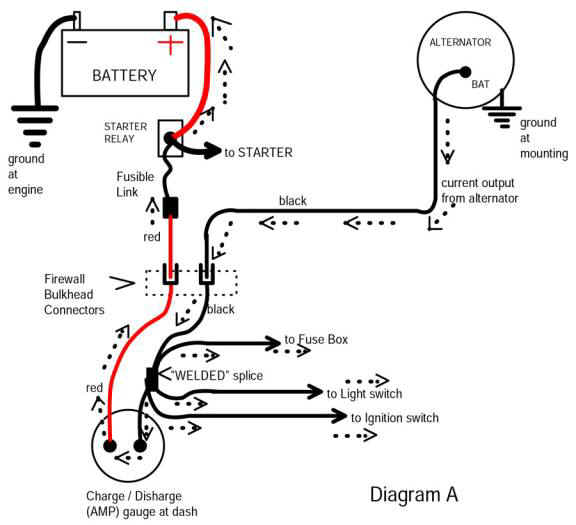
and the simplified diagram is a VERY good way to understand:

Notice that power comes off the battery...............goes to the big stud on the relay.........through the fuse link...................then through the bulkhead connector (RED wire)

THIS IS your first suspect

Next it goes to the AMMETER. The ammeter connections and the ammeter itself are suspects two and three

From there it goes to the FACTORY WELDED SPLICE in the ammeter black wire. It is rare, but this splice CAN fail.

This splice branches off and feeds several things..........

the "hot" fuse panel buss

the ignition switch infeed

AND the headlights.

So if you have no lights, it is almost certainly between there and the battery

'S why I mentioned to do your checking with something "heavy" (like the lights) turned ON. This places a LOAD on the system. Not only will this help you find the bad connection, but if you "wiggle test" a connector, you will smell, see, and hear the spark!!!! As well as see the lights come on if you are in subdued lighting.


You have a factory shop manual?

Here

http://www.forabodiesonly.com/mopar/showthread.php?t=244981

Direct linkeypoo

www.letsgocomputers.com/docs/1973dodgebody.pdf

www.letsgocomputers.com/docs/1973dodgechassis.pdf

The diagrams for 73 were "improved". They start on page 8-152 These are good and bad. The "improvement" makes stuff easier to find if you are trying to find "one thing" but it also makes things harder to follow in other ways

NOTICE in these diagrams the circled "CE" (means connector, engine) and "CI (connector, Instrument). These are connector terminals. Starting on page 8-164 are the diagrams for those connectors The bulkhead connector, EG is "CE-2"

303irsk.jpg


SIMPLIFIED but NOT ALWAYS complete diagrams are the ones at MyMopar

http://www.mymopar.com/index.php?pid=31

These two diagrams

http://www.mymopar.com/downloads/1973/73ValiantA.jpg

http://www.mymopar.com/downloads/1973/73ValiantB.jpg

These diagrams do NOT SHOW every terminal and connector, but are sometimes easier to follow
 
These are crops from the factory diagrams. Ignoring the 60A alternator wiring........

Notice how closely this follows the simplified diagram of the MAD article. Follow along. I have ignored the 60A optional wiring. The circled junction is the "welded splice" which is in the black ammeter wire up under the dash. Start at the battery A no10 RED goes from the battery to the starter relay "big" stud.

Look up CE5 and CE3 on page 8-164 and you'll see what they look like

From the relay stud a no 10 RED goes off to the (tagged) FUSE LINK and right through the bulkhead connector at CE2 J. This is "J" in the bulkhead connector. That goes directly to the ammeter, through the ammeter and out the ammeter on the BLACK wire R6C-12BK which goes up to the CIRCLED welded splice. WE ARE STILL UNDER the dash

From there the wires branch out to the three going off the page.


Now here we have left the page above, and gone two pages down to 8-156. The three wires from our WELDED SPLICE have been "fed through" the page in between. Here is where they go Q3-12R feeds hot power to the "hot" buss in the fuse box

L1--12BK feeds hot power to the headlight switch for ONLY headlight power, NOT tail, or park

J1-12R feeds hot power INTO your ignition switch. This would be the only huge RED wire at the igntion switch connector


Thank you so much everyone for the diagrams. I was able to drive it home. My father who is an electrical guy (he completely rewired a VW I built from scratch) stopped by to give me a hand. He did some poking a probing and worked the terminals a bit and checked all connectors etc. we ruled out ignition and we think it was the original 73 terminal connectors. So I swapped them out, cleaned terminals and made sure all connections were tight and clean. Drove it about 40 miles and everything seems A-ok now. I will be holding onto those electrical diagrams. Thanks again everyone!
 
-
Back
Top