i need help soon.. electrical problem

-

Promark

Well-Known Member
Joined
Mar 7, 2010
Messages
61
Reaction score
0
Ok so i put a new alternator in my car and everything started up fine and all my lights were nice&bright.. idle sounded good too.. but after about 3-5 mins on, the cars headlights strobed out and they went out.. my taillights also went out and my 2 gauges lights too.. but my dome light still works!.. i checked the fuses and all of them were still good.. so now i dont know what is wrong with the car... its a 67 barracuda with a 340 in it.,they didnt have an alternator for a 340 v8,,, so it was between a 276 v6 alternator or a 383 v8 alternator.. so i bought the 383.........., any feedback, ideas or suggestions welcomed!!!!!!!!!!!!!!! thanks!!!
 
You may have a voltage regulation problem and may have blown up some lamps

A few points: You still using the 69/ earlier regulator, looks something like this?

oe-style-voltage-regulator-for-1961-69-mopar-b-body_370303095941.jpg


and you still using a stock type original Mopar alternator?

If so, don't get flustered with the application. ANY Mopar alternator from 62 up into the 80's will work, even if it's the 70/ later isolated field (incorrectly called dual field) as you can just ground one field terminal if using the older 69/ earlier alternator

First thing you need to do is measure charging voltage at the battery with a voltmeter.

Get the car running, "ease" the throttle up while watching the meter, and don't let the meter go above 16V or so if it starts to climb

If it does that, then there is something wrong I.E. the system is not regulating, and you need to fix that BEFORE you worry about fixing the lights.

IF the voltage IS high---goes above 15 and higher as you increase RPM, one of the first things to do is check FOR SURE that you have a good ground on the regulator
 
It was over charging. If you were lucky, bulbs are the only things that blew.

Is the new alternator a later model double field unit? If so, one of the field lugs have to be grounded to the block, the other is connected to voltage regulator.

Make up a short length of #14 wire with a female connector, and the other end an eye large enough to be secured to a bolt near by the alternator as shown below:
100_1267.jpg
 
The picture u posted where is that thing located
 
I'm also running a electric ignition. It is not the stock ignition
 
In the photo, there are two "push on" connectors on the alternator, one blue, the other green. IT does not matter, one of them must be grounded. IF you have a 69/ earlier alternator, one brush will already be internally grounded.
 
Since you already have electronic ignition upgrading to a solid state isolated field regulator would probably be best. your original altenator has a single green wire from the rgulator to one field terminal. The original regulator has a blue at the top and a green at the bottom. The solid state regulator will use these same wires and you'll simply splice the blue at the regulator to add approx. 7 feet of blue wire to the second field terminal on the altenator. Because this added blue wire will be hot in run, I take the time to back the right branch of the engine harness out and over the left fender, untape it and tape the blue wire in with like factory. the original terminal that you cut off the green wire at the regulator will be reused on the alternator end of the new blue wire.
 
The long odd color green wire with blue shrink wrap in the photo comes from voltage regulator. I replaced it and couldn’t match the color exactly. The short blue wire from left field terminal with a black factory type connector is grounded to the block. It doesn’t mater which one is grounded, I chose the nearest to block for ecstatic reasons only.

RedFish:
Since you already have electronic ignition upgrading to a solid state isolated field regulator would probably be best. your original altenator has a single green wire from the rgulator to one field terminal. The original regulator has a blue at the top and a green at the bottom. The solid state regulator will use these same wires and you'll simply splice the blue at the regulator to add approx. 7 feet of blue wire to the second field terminal on the altenator. Because this added blue wire will be hot in run, I take the time to back the right branch of the engine harness out and over the left fender, untape it and tape the blue wire in with like factory. the original terminal that you cut off the green wire at the regulator will be reused on the alternator end of the new blue wire.

I’m trying to translate what you have written… I only have ½ cup of coffee down the gullet so far this morning, so I bit slower, than my usual thick headedness.

Just to clarify are you saying to run two leads from top of regulator, (reusing factory connector because it plugs in nicely with new electronic regulator’s pigtail), where one conductor goes to field #1, and the other to field #2 on the alternator, and skip the grounding method of one of the field lugs? Than incorporate the additional conductor into the existing harness bundle for neatness?
 
Yep, The blue or blue with white traccer at the top of the original regulator is hot in run. The factory extended that same wire to the alternator field terminal. Taping it in is both neatness and added protection against chaffing/damage/ short circuit.
 
wjar, maybe this will help?

Dual_Field_Alternator_Wiring.jpg


The two (70/ later, electronic) regulator terminals connect to the two field connections on the new (70/later) alternator. Does not matter which goes to what.

The "top of the triangle" of the regulator connector is BLUE and also goes to switched ignition, which is the same place the old regulator hooked to "ign."

One thing you MUST do is check for ground and harness voltage drop which (if there is excessive drop) WILL cause overcharging.

To check both the hot and ground side of the circuit, do this:

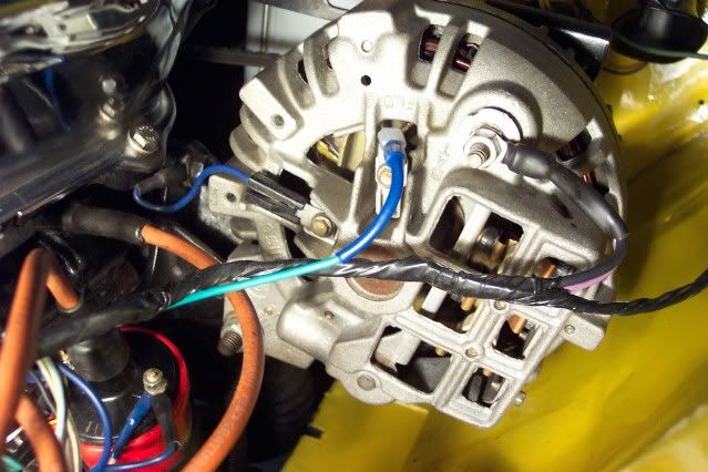
Turn the key to run, engine off. Put one probe on the battery positive, and the other probe on the blue wire at the field of the alternator.

You will be checking voltage drop for the complete circuit path from the battery--fuse link--through the bulkhead--through the ammeter circuit--through the ignition switch and it's connector and back out--back out the bulkhead connector --to the regulator, the ignition, and the field terminal

You are hoping for a VERY low reading, and zero would be perfect. Anything over .2V (two TENTHS of a volt) is a concern, and over 1/2 volt is way too much If you read above .2, check that circuit path, especially the bulkhead connector and the ignition switch connector

Next, check the ground path. Start the car, get the engine running to simulate "low to medium cruise" and check the battery voltage with your voltmeter to make sure it's below betwen 13 and 16. I chose 16 because of your charging issue, and we "aren't there yet." A properly operating system would be more like 13.5-14.5

Now, put one probe right on the negative battery post. Stab the other probe onto the regulator case. Make sure you stab through any paint, rust, chrome.

Once again, you are looking for a very low reading, and above .2V shows the ground between the battery and regulator needs improvement.
 
Promark,
Everybody here loves to help, but you need to reply to their questions or they will soon lose interest.
Does your voltage regulator look like the one posted?
Does your alternator look like the one posted (square back) or is it the earlier round-back type?
Do you have a multimeter? It is an essential tool. $3 at Harbor Freight.
We can't assume anything based on the year of your car since many electrical systems have been upgraded, ex. your electronic ignition.
I think over-charging is the likliest fault.
Have you checked the bulbs in the failed lights. Is the filament gone? Do you measure a resistance?
 
im not sure what my voltage regulator looks like cuz i cannot find it. theres one thing that i have that might be it and its near the master cylinder but im not sure
my alternator does not look like the one in the picture. it has a rounder back. no i dont have a multimeter... the headlights r sealed so idk and im not sure about a filament?.. i want to just take it to my mechanic but i recently moved and hes about15 miles away and im being told that the car can start a fire now easily..
 
i plugged the wires from the square one i had exactly the same way into my newer round one.
 
Here is an electronic voltage regulator designed as a bolt in to replace mechanical type voltage regulator. The top pigtail will receive stock stile connector from pre electronic Mopars. I have used these devices before on my 67 in conjunction with two terminal ballast resistor, orange spark controller, and duel field alternator with one grounded field lug.

I also had over charging problems, but not caused by voltage regulator, but from trying to power an electric choke directly from high side of ballast resistor which caused a voltage drop in the circuit that the voltage regulator read as normal system voltage. Because it was reading low voltage in ignition circuit, it instructed alternator to put out more voltage to bring the system up to normal charge of 13.5-14.5 v. Actual voltage measured at battery became 15.7v which boiled the battery, and shortened light bulbs service life. I corrected the problem by installing a relay that fired off from ignition circuit, and powered choke directly from alternator’s power lug.

In order to check and diagnose any electrical circuitry one needs to have a few basic tools: Volt Ohm Meter (VOM) $10, test light with probe $6 (looks like an ice pick with a wire hanging off one end, and a light bulb in its handle), and a wire diagram of one’s car FREE. Don’t be intimidated by wire diagrams, They are just a map of your car’s circuits in pictorial form, listing wire color, and size.

Back to the over current problem:
Also you need to make sure all the ignition circuit devices have good ground with little to no voltage drop. This can be easily accomplished by making up a grounding circuit that connects to each chassis or outer body of the following: voltage regulator; spark controller; alternator, and connects to negative battery terminal with # 16 or #14 gage wire using crimped on eyes of a size that will accommodate bolts securing the above devices. This levels the electrical playing field so to speak for each device. You have heard the computer line: garbage in, garbage out, well it the same for electrical devices that regulate voltages, that’s why we need to eliminate voltage drop to ground.

Once you find and identify your regulator, and get a VOM, we will be able to provide better guidance.
 
ok im sorry guys. its that i read these post and im like -_____-
i am not mechanic friendly but i am trying to be but have of the stuff everyone saying i understand.
 
One of the first things we need to do is determine whether you have the 69/ earlier voltage regulator or the 70/ later.

I already posted what a 69/ earlier looks like:

http://www.musclecars.net/parts/par...tor-for-1961-69-mopar-b-body_370303095941.jpg

and below is the '70 /later:

(Notice that it looks exactly like the drawing I posted showing the wiring for the later system)

http://ecx.images-amazon.com/images/I/41tepZX4+FL._SL500_AA300_.jpg

Another thing---do you have a Chrysler shop manual? There are several posted on this thread. Since you MAY have the later charging system, and you seem to have the electronic ignition system, download the 72 manual for that part of things, and one of the earlier manuals for the rest of your car:

Scroll down through the thread, there are several posted

http://www.forabodiesonly.com/mopar/showthread.php?t=132309&highlight=manual,+download
 
half of the stuff.. i dont understand*

Maybe I should apologize. I try to keep posts short and simple.
Too much info can be both un-nessesary and overwhelming.

You'll have to have a multi meter to properly dianose most electrical problems just like you would have to have a hammer to drve nails.

There are only 2 shape/size voltage regulators. You will have one or the other. Black box like pictured above or one that looks a bit like the igbition module. Connector plug in the face side of it has a metal retainer clip.
Hope this helps
 
My voltage regulator looks like the 70's one... The second link... But when I go get a new one at the auto store it looks like the 1st link
 
My voltage regulator looks like the 70's one... The second link... But when I go get a new one at the auto store it looks like the 1st link

Well, what are you asking for? You cannot ask for one and tell the guy "my car is a 67" because the OLD one is what you'll get. The "70's" one is exactly that--if that is what is on your car, then someone has upgraded the system to a 70/ later regulator/ and alternator, and that is what you need to ask for.
 
So I buy that install it and then do the thing with meter?
 
I realize that your electrical skills may not be that great, but you need to determine IF you can, that you need a regulator BEFORE you buy one and put it on the car

I suggest you re--read this thread, carefully, and try and give us a detailed post about where you "get lost." Or let's start fresh right from here. What have you checked so far, and what have you determined?

There are some basic "firsts" WE NEED TO BE SURE OF in concrete

Question1:

Does your alternator have one or two "push on" field connections?

IF it has two "push on" field connections, is one of them jumpered to ground, or do both field wires lead off into the harness?

Question2

BE SURE what you have for a regulator. You seem to think it is a 70 / later as per the photo? Does it have a triangular connector like in the photo?

60-69 regulator, for alternators with ONE ungrounded (push-on) field connection:

oe-style-voltage-regulator-for-1961-69 mopar-b-body_370303095941.jpg


Replacement aftermarket solid state regulator fits same as above:

3690732_large.jpg


The regulator below fits 70 and later. The alternator MUST have two "push on" field terminals:

Ignore the color and part no. It is probably black. NOTE the shape of the connector

P3690731-1.jpg
 
So I buy that install it and then do the thing with meter?
Yes. If the wiring is correct and the voltage regulator is working correctly, one of the small terminals (blue wire) on the alternator should read constant battery voltage (~13.4 V) and the other small terminal (green wire) will read a low voltage (<10 V) when the alternator is generating current (turn on headlights and all accessories) and close to battery voltage when no current is needed (turn off headlights). Connect the multimeter black lead (-) to battery- and the red lead (+) to whatever voltage you want to measure. Of course turn it to "VDC" and "20" range (or higher).

If you want to save money, buy the multimeter first and see if the problem is in the wiring. Unplug the connector at the voltage regulator. Unplug the green wire at the alternator. Turn the multimeter to "ohms" (upside-down U symbol) and lowest range. Connect black lead to battery- and the red lead to the green wire of the voltage reg connector. If you measure less than 100 ohms, that means your "field control" wire is shorted somewhere. That would make the alternator put out max current.

On a side note, RedFish is slightly wrong. As 67Dart273 posted, there are several styles of the "pre-70" voltage regulator (i.e. "grounded field" or "1 field wire"). He showed the factory original and one electronic replacement. I have an electronic one on my 65 Newport that is a silver box about the same dimensions as the 70+ one, but with the same connectors as the old factory box. Those are still available (~$25) and are best for people upgrading who don't care to run a new wire and hack up their wiring. Such "high side throttling" should work as well as the 70+ type's "low side throttling". To tell if you have the 70+ style box, go by the triangular connector with 2 pins, not the shape or color of the box.
 
-
Back
Top