Regulator Problem '68 Barracuda

-

fstfsh

Member
Joined
Sep 20, 2014
Messages
19
Reaction score
0
Location
louisville
please, can anyone help me with this hot mess?

my 1968 barracuda notchback is having charging problems. the dashboard ammeter shows discharge when i am driving. i know something is wrong because the headlights are dim, the turn signal makes the ammeter needle bounce, and my drip-charger detects battery discharge when hooked up.

the car has a 340 with a six barrel and an electronic ignition.

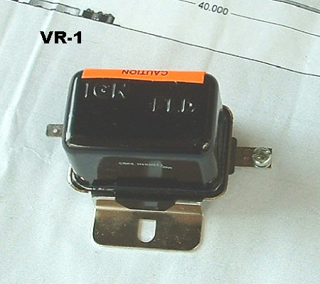
autozone ran a test, which found that the alternator was at about 13 volts but the regulator had failed. the regulator in the car is relatively new but the same kind in the car when i bought it. it does not look like a mopar regulator. it also does not seem to be hooked up like i have seen in diagrams on this site for pre-1970, post-1970 and modified regulators.

one lead goes to the positive terminal on the battery. i cannot trace the other leads. here are photos of the regulator hooked up, one of the regulator off the car and the back of my alternator.

any idea whether this setup is correct and could be the cause of my discharge issue?
 

Attachments

  • IMG_2887.jpg
    38.1 KB · Views: 496
  • IMG_2890.jpg
    34.7 KB · Views: 455
  • IMG_2889.jpg
    34.5 KB · Views: 429
The picture you have is of the starter relay. The regulator would be mounted on the firewall between the wiper motor and master cylinder just a little farther down.
 
if someone had the dash out and connected the two wires going to the amp gauge backwards it will read as it was discharging.
 
this looks like a "B" circuit alternator. Which means that only one wire will be hooked to the back of the alternator "fld" terminal. this green [14 gauge or smaller] wire will normally lead back to the "rectangle" black regulator on the fire wall. This is marked IGN and FLD. The IGN terminal [blue wire] will have Key hot battery voltage while the FLD wire [green]will vary in voltage due to the demands of the battery/load on the vehicles electrical systems. If you wanted to check the alternator output: Apply battery voltage to the FLD lead and with a volt meter hooked to the battery, engine running approximately 2000 rpm, watch the volts, it should climb, do not let the voltage climb above 16 volts max! [14 - 14.5] would be better. This will NOT tell the output in amps of the alternator but will give you some idea of the "complete" system operation.
 

Attachments

  • Hemi Looking good for Chip 2013.jpg
    55 KB · Views: 386
  • Dart original wiring page 2.jpg
    93.1 KB · Views: 510
It turns out I have a p-3690732, which from what I have read is a constant voltage regulator. I also have read that it would produce too much for street use, although the car seems to be discharging rather than overcharging. Another writer says that the regulator is epoxy coated and does not ground properly unless the back is sanded to bare metal.

Thoughts?
 

Attachments

  • photo.jpg
    39.4 KB · Views: 380
Hi,

Yes, I would try that getting the paint out of the way idea first. Also, your photo of the alternator shows it to be a "round back" type which is correct for a 68. It should have two wires attached to it. One is the heavy black wire attached to the output stud and the second should be a green wire attached to the single field terminal. In the photo it looks like there are some wires dangling near the exhaust manifold. If there is a green wire there that is not hooked up you will not get any alternator output. Beyond that, try the test outlined by Rob in his post above, that should tell you if the alternator is good and you have a wiring or regulator problem.
 
OK. I took out the constant voltage regulator and installed another I got from Classic for the year and make. I am having the same issue - battery is discharging when I run the car. When I put on the headlights, the car quits. I have to jiggle the bulkhead connector and fusable link to get the power back on. And the car starts.

here are some numbers:

Here is what I have found:

The battery tests at 13.03 volts

Between the negative post on the battery and the field post on the regulator - 9.47 volts.

Between the field post on the regulator and the regulator screw into the body (ground) - 9.53 volts

Between the alternator positive and battery negative - 12.71.
 
It doesn't seem to be charging. Turn key to run, engine stopped. Check power at the black wire flexible connection at the VR. Should be very close to battery voltage. This is, in fact "switched ignition run" meaning it is getting power from the key in "run."

The stud/ nut terminal should show a little less but still close to battery in that case.

Below is what your old/ original regulator looked like. you can see the "push on" terminal says "ign" and the screw terminal says fld, "field," green wire going to alternator field. The correspond to the flex wire (ign) and stud (fld) on the blue one

Make SURE the blue one is grounded.

VR_1.jpg


Next thing to try is to bypass the regulator to test. Get / rig a test lead long enough to go from the alternator field terminal (push on) to the battery or "big stud" on the STARTER RELAY. Hook that jumper up, hook your voltmeter to the battery, and run, slowly bring up RPM and watch meter. Meter should climb above 12.6 Turn on Headlights. At a good fast idle, the battery should still climb above 13 easily with a bit of RPM.

If this test does not cause charging, switch your voltmeter to the alternator output stud (big black wire, big stud) and retest. If voltage stays low, say, 12, or below, alternator is not charging. If it climbs way high, above 16, you have a problem in the output circuit (charging line) of the alternator on it's path to the battery.

===================================

Now if the above test indicates a good charge, you are back to the field circuit and regulator. Next, remove the clip lead and hook everything back up. Put your meter on the battery. Unhook the VR connections, and jumper the two harness wires together. This is feeding ignition power directly to the field. Repeat the test. If it charges, and the VR ground is certain, replace the VR. If it does not charge, you have wiring problem in the field circuit.

The stud connection is one wire goes to the field, easy to check

The IGN connection goes back and ties in with ignition. If your harness is chopped up some, this might be a problem.
 
Hi,

Yes, I would try that getting the paint out of the way idea first. Also, your photo of the alternator shows it to be a "round back" type which is correct for a 68. It should have two wires attached to it. One is the heavy black wire attached to the output stud and the second should be a green wire attached to the single field terminal. In the photo it looks like there are some wires dangling near the exhaust manifold. If there is a green wire there that is not hooked up you will not get any alternator output. Beyond that, try the test outlined by Rob in his post above, that should tell you if the alternator is good and you have a wiring or regulator problem.
In the pic it looks like the second alternator wire hooked up is blue...disconnect the blue and plug in the green wire.Hope this works.
 
In the pic it looks like the second alternator wire hooked up is blue...disconnect the blue and plug in the green wire.Hope this works.

That might be a good point, but I don't see a green wire. The green should be a single wire with no other wire spliced in. That second connector there is ???
 
thanks all! i will post some clear photos of what i took out and what i installed.

if you would be so kind as to clarify what you mean by this: "Below is what your old/ original regulator looked like. you can see the "push on" terminal says "ign" and the screw terminal says fld, "field," green wire going to alternator field. The correspond to the flex wire (ign) and stud (fld) on the blue one

Make SURE the blue one is grounded."

on the voltage regulator that i installed, the blue wire - push on - goes to the ign. the green wire to the stud. isn't the unit grounded through the screws to the firewall?

Yes and no. MUST be clean and tight, scrape off paint!!!
 
really? scrape off paint on the firewall? not enough contact through the screws?
 
Well then don't I really don't care. Those blue regulators are alleged to have epoxy paint and "might be" a problem according to what I've read
 
no offense meant. i am not using the blue regulator but the black one. i thought the screws would provide enough of a ground. but first i will try what you suggested in your list. thank you.
 
-
Back
Top