run stand

-

Mopar Al

MOPAR AL
Joined
Dec 21, 2008
Messages
767
Reaction score
102
Location
Western Pa
I just built this run stand and wanted to share pics. Now the question is does anybody have a wiring diagram? Want to use Tach, Oil pressure, Temp. Need to know wiring for ignition, Etc. Thanks, Al.
 

Attachments

  • 252.jpg
    99 KB · Views: 988
  • 253.jpg
    92.7 KB · Views: 926
  • 254.jpg
    88.4 KB · Views: 876
  • 255.jpg
    101.6 KB · Views: 918
that is very cool , great job. im going to be firing mine up outside the car so im looking forward to seeing how this will be set-up.
 
I just ran mine mounted to the K frame on a cart.Wiring pretty simple I have a harness made up that I can send you with a universal key switch.
All you will need is the ballast - ecu - starter relay - battery cables.I didn't use any but I would just use mechanical temp and oil gages which I may have some of those around also
 

Attachments

  • motor%20002.jpg
    89.3 KB · Views: 911
I just ran mine mounted to the K frame on a cart.Wiring pretty simple I have a harness made up that I can send you with a universal key switch.
All you will need is the ballast - ecu - starter relay - battery cables.I didn't use any but I would just use mechanical temp and oil gages which I may have some of those around also
did you use an alternator?
 
did you use an alternator?


You shouldn't need to have to bother hooking one up as you could run a battery charger if you planned on running it for any real length of time aside from break in. A good strong battery will go far in this situation.
 
Havent really thought about alt yet, but I think it would be easier to just charge the bat ocasionaly, and probaly less wiring. Always open to new ideas. One problem was the bat was on the left rear of the stand. test fit my TTI headers. Way too close to the bat. Just got done moving the bat to left front of the stand. All is good now. Cut,Weld,Cut,Weld, steel is pretty forgiving.
 
You shouldn't need to have to bother hooking one up as you could run a battery charger if you planned on running it for any real length of time aside from break in. A good strong battery will go far in this situation.
i will be running mine for around 20 minutes. just long enough to break it in. i want to make sure all is well before pulling the 360. :D
 
idk , just a question. ive never ran an engine outside the car before. i wasnt sure if it needed to be there to complete the wiring

not trying to threadjack you Al. i was going start a similar thread and coincidently, i saw this one this morning lol
 
That is cool! temp, oil and tach. Run points and its a 1 wire hookup, power to coil! You wont burn it running it for 20 minutes...put it through a light switch so you can break it and kill the motor. Check this guy out, he states (4:40) "..its in pretty good shape, EXCEPT it has a Chrysler 225 slant motor in it..." C'mon! "Not too good on the gearbox but I bet it has loads of power...." http://www.youtube.com/watch?feature=player_detailpage&v=eQ5yRXiEIwg

I couldnt find the Aussie that had a V8 motor w/trans running on the floor of his garage and it was rolling around when he revved it.....
Phista, can this be done with an electronic distributor without the EI box wired up ?
 
Beautiful engine stand Al!

I believe that 67dart273 has a thread or 2 that shows how he has wired up an engine for a temporary purpose. Sorry I will try and find the thread when I get a chance.

Wiring up the temp, and oil gauges should be straight forward as you will be wiring from the gauge to the respective sending unit. When I bought my auto meter gauges it was pretty easy.

Nice Stand!

yes that engine stand is friggin sweet.
i remember seeing Dels diagram somewhere but i cant find it now. hopefully he will chime in
 
I wired up a temporary box to fire up engines and ALSO to act as an emergency ignition to carry in the car

This is the "original" style, or "large cap" GM HEI module. I used a Mopar factory coil and no ballast. You must ground the module through the mounting bolts, mount it on some sort of heat sink (aluminum box in this case) and use the thermal grease suppplied with the module. Be sure and hook the Mopar dist. connector "as drawn" for correct dist. phasing.

With mine, you just hook up coil wire, distributor, yellow to battery, green to ground and you have ignition. (I used yellow and green because that is the first couple of clip leads I came across. "Junkbox" mentality.)

So far as wiring your panel, this is going to depend on your gauges. If at all possible I would use mechanical oil and temp gauges, as they are more foolproof, and require no wiring. All this leaves is ignition and start.

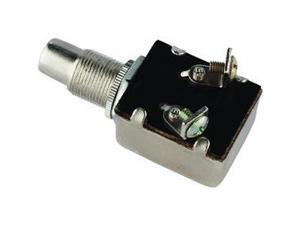
Just buy a big heavy starter switch from the parts store, and a good quality toggle switch. Wire from the starter battery post to the both switches.

Remaining terminal of the toggle (ignition) then goes to the power in of the HEI diagram

Remaining terminal of the starter button goes to the solenoid of your starter.

I don't bother with any of this wiring. I just hook the battery to the starter and the block, clip lead the ignition in place, and use a screwdriver to short across the solenoid terminals.

zu5qn8.jpg


hwlcfa.jpg


Most any parts store sells universal starter switches like these:

A0MZ_1_20120626_9524131.jpg


Or better yet, just buy a remote starter switch that you can use later when working on the car:

You just clip it to the two starter posts

41tCHcnENDL._SL500_AA300_.jpg
 
will this set-up work like this . the ECU mounted on the engine block with the ground from the battery. the "E" representing the engine. the blue wires representing the wiring to the push button starter. can i tie the "start" and "run" wires together and connect them to the positive side of the battery. im asking because this is what i have to work with outside of putting this in the car. i have manual oil and temp gauges along with a push button starter

again i apologize for the thread jack, i should have just started my own

sorry for the ghetto drawing LOL
 

Attachments

  • diagram2 copy.gif
    10.9 KB · Views: 1,165
I used the diagram straight out of the "Engines" book. I did run a alternator. The engine was actually in the car. (Bad harrnass.) the gauges are simple to hook up. Just take the time and care to run enough wire on everything to make it a neat and tidy package so it looks good and safe. To start the engine, I went to Summit racing for a push button and simply wired it inplace of the key switch.
 
will this set-up work like this . the ECU mounted on the engine block with the ground from the battery.

I would not bypass the ignition resistor, especially if you are going to run the engine for 1/2 hour or so to warm up and break in the cam. If you are going to use any ignition with a ballast resistor, you need some way to bypass the resistor for start, and put the "run" in place

There are several ways to do this:

1---One simple way is with a big diode which you can buy at radio shack. Get the largest current rating they sell with at least 50V PIV (peak inverse voltage) rating, or more.

Wire from the starter solenoid post to coil positive, with the band (ring) on the diode toward the coil.

2---Use a Mopar starter relay or Bosch relay for ignition bypass. You can hook it up in parallel with the starter relay so that both the solenoid and the relay fires at the same time.

3---You can use a Ford starter relay--the "I" contact goes to coil positive, and the two large terminals fire the Mopar starter, taking the place of the original start relay

Here is the simplest way I know. Pay attention to the upside down U on the resistor, which orients it to proper wiring, not shown in the diagram you posted
 

Attachments

  • _MG_6227.JPG
    153 KB · Views: 756
hmm , thanks Del, it looks like the hei would be a much more simple way to go. its not that i want to use a ballast, more in the fact that i have a 5 pin ECU box, a pigtail , and a ballast laying around. i was trying to find an easy way out using what i have
 
I just ordered casters last night for a run stand.

Here is a pic of my willys that I started in the frame, concept is the same.

1001706f.jpg
 
hmm , thanks Del, it looks like the hei would be a much more simple way to go. its not that i want to use a ballast, more in the fact that i have a 5 pin ECU box, a pigtail , and a ballast laying around. i was trying to find an easy way out using what i have

In reality, all you need with/ without a ballast is about a 2---5 buck diode from RS and one more wire, LOL

I'm not necessarily recommending RS, it's just that they are "available"

And as Pishta said, if you have a breaker point distro lying around, that eliminates a whole bunch of wiring.

http://www.radioshack.com/product/i...nSession=1&filterName=Type&filterValue=Diodes
 

Attachments

  • diode.jpg
    25.9 KB · Views: 629
Here are some pictures of my run stand. I was mounting a 360 to test run and was having to modify some things since I run different engines on it. I always wire the stand exactly like the car, with the alternator and ignition I plan to run. If you are going to test run the engine, this is the time to iron out any electrical problems and verify sensor operation.
 

Attachments

  • HPIM1127.jpg
    156.4 KB · Views: 666
  • HPIM1130.jpg
    133.4 KB · Views: 675
-
Back
Top