70 duster: updating, and a no-dough pro-touring makeover

-
Sorry to hear that. Hope you heal up well and there are no lasting effects.

Thanks for the info!
 
My last update was 9/5/13!!!

Holy cow. Two years, three months, ten days.

I should probably account for that amount of time. Most of you guys have seen other stuff I’ve been working on, but for those of you that didn’t, ill provide links.

Short version: medical, house, life, automotive ADD.
Long version:
I’m a mental health clinician for my day job, ran the local hot rod shop for years for a side business, father, husband, son, and I think part magpie (ooh!! Shiny!!!). my day job has become more and more involved since moving into residential services, often requiring 80 hour weeks, no sleep, high stress, etc. very consuming job. Which means less time for other things. Also, my daughter has been becoming more and more involved in various activities, which I also like to be involved in to support her. So when I’m not at work, I’m there. And when I’m not doing that, I build cars for others. And when I’m not doing THAT, I’m fixing my own stuff, and renovating the house. Obviously, not a lot of hours left over there. Well, couple of years ago, it became apparent that I needed to become more involved in the bodywork on my El Camino. As seen here: https://grassrootsmotorsports.com/f...beater-20-64-el-camino-this-time/60101/page1/ so that sidetracked me considerably from the duster. Spent a lot of hours at the body shop, and a LOT of money. During that period, driveline specialties rebuilt the rear end again, making it quiet. Apparently their previous supplier had some troubles with the gears, and then went out of business. They honored it anyway. Very great guys. I also realigned the car, and daily drove it through that January and February when my daily was down. I also broke a lowering block while dialing the car, and wound up doing the hanger flip instead. Lowered the rear too much, but never got around to a solution.
In April of 2014, I was helping brother Dustin build his woodshop. It had started raining, and we were almost finished. So I decided to be superman. Carrying a couple of sheets of¾ ply above my head in the wet grass, I slipped. Hurt my left knee and ankle pretty bad. Couldn’t push in the clutch anymore, so the car got parked. I limped along for a few months, and finally went to the doctor. Turned out that I had shattered my left ankle, and that my knee would mostly heal once it was rebuilt. So September of 2014, I had reconstructive/repair surgery. I was able to try to drive the car again in January 15. I managed to make it to Indian trail (about 60mi) before the interior filled with smoke. Dash fire. Crap. So had it towed home, and put it in time out to think about what it had done. After fighting, and losing, with the comp claim through insurance, I was pretty disgusted. I also had to rebuild my deck, and the shop needed a major overhaul before I could really work down there. So we jerry rigged the car back together to run long enough to drive it down to dads. That was in April or so of this year, at the same time that I decided to close down the shop. It was no longer worth the time/money that it was taking/making. No longer made me happy like it once did, either. The duster has been living in the corner down there since. While it was out of the way, I did this: https://grassrootsmotorsports.com/f...not-the-grosh-caliber-but-still/103346/page1/
So, with those small projects finished up, and a status update on my life out of the way, I guess we get back to the intent of this thread: converting a duster to a pro-touring car, on a budget.
Where the car left of:
Burned up wiring harness. Bad vibrations in the driveline. Stiff clutch. Piss poor running. Dead spot in steering. Back end too low. Various creaks/bangs/pops from the suspension. Ac intermittent. Electric fans making noise. Brakes making noise. Parking brake inoperable. Various leaks. Drivers side window tracks need work. Console needs dyed. Needs cleaned everywhere.
The previous budget: 7996.27
Money spent (the best I can remember)
Edelbrock fuel rails: 110
Tanks inc in tank pump: 235, summit racing
Roll of steel fuel line: 21 (oreilleys)
91 corvette ECM with MEMCAL 45 (carguts in south carolina)
Adjustable fuel pressure regulator, ebay 21
Ez mini 21 circuit harness, ebay 135
Kenwood 3 channel amp, swap meet, 20
Polk dash speakers, pull a part 12
Memphis belle 6x9 speakers, free
4 gauge amp wiring and terminals, free
Battery jump terminals, 17 ebay
New total: 8612.27
So this past month, I decided it was time to bring the old girl back out of the time out corner. I started in on finally finishing the intake that I began to convers for port efi. It needed lots and lots of work to finish. So I pulled it, my magnum fuel rails, etc. off the shelf. I also learned, somewhere in the last couple of years, that the GM ECM I plan on using does not like a fixed fuel pressure. The ecm works better with a vacuum referenced regulator. This meant that the single inlet, return less, magnum rails would need to be modified to work. Instead, I spent the good money on a set of edelbrock aluminum fuel rails. Easier to set up as a return style, easier to mount, and look better.
Anyway, I pulled the parts out of storage, and this is what met me:
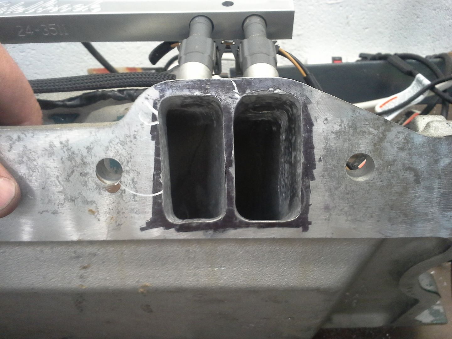
Half finished, mostly butchered intake.

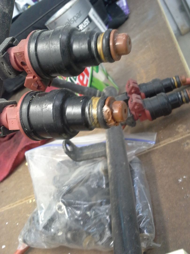
Melted injector pintles on my 30lb injectors:

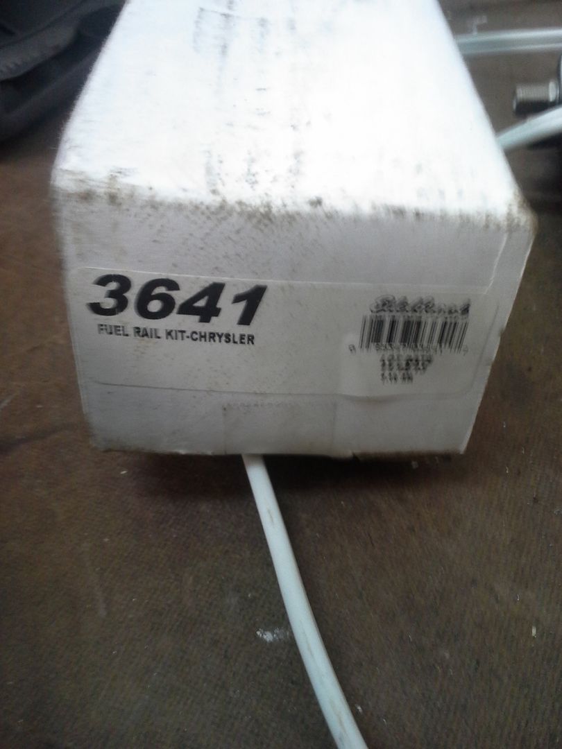
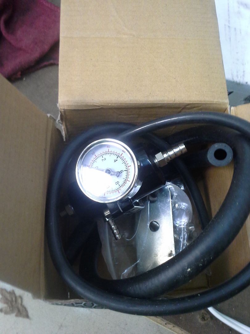
Shiny box of fuel rails:

Ebay sourced vacuum referenced fuel pressure regulator:

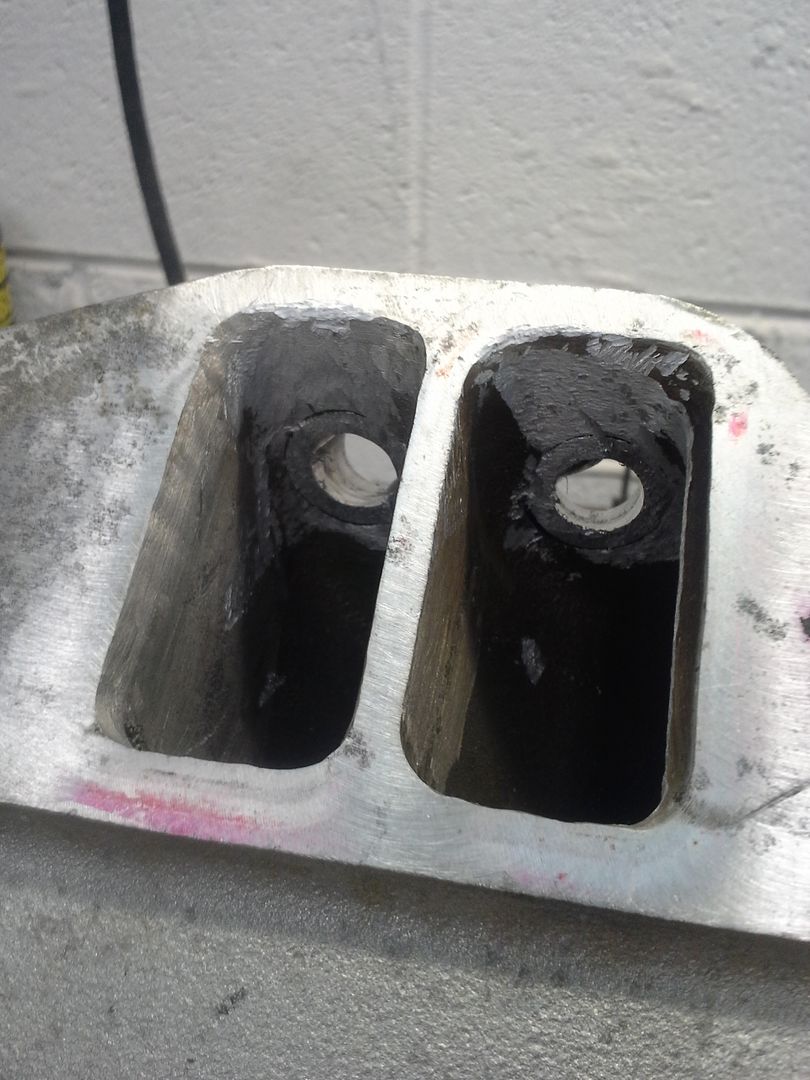
So I got to porting. Took more than a couple of hours, but the intake runners/bungs are done. Still need to decide what to do about the plenum, if anything.

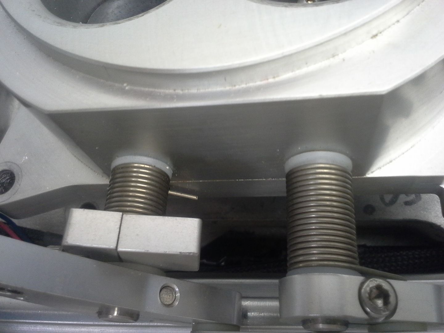
Mock up with a spare set of ls1 injectors (26lb), edelbrock fuel rails. The 30lb test out fine, and will be rebuilt with new o-rings and pintle caps. What happened was that when we welded the bungs in, we used the rails and injectors as a jig. Too much heat. Only a few got melted, and those seem to be fine.

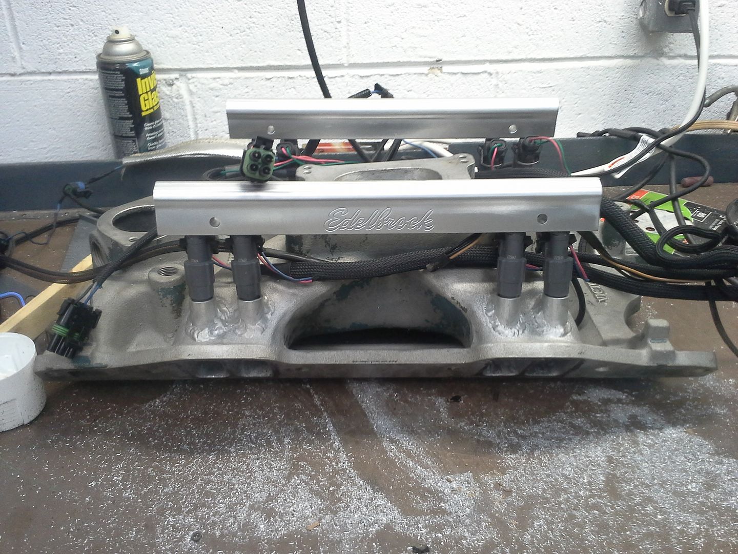
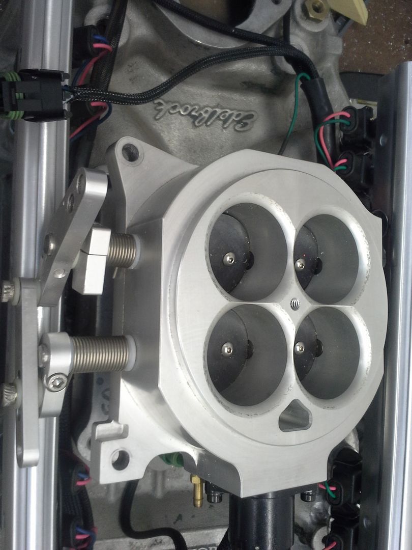
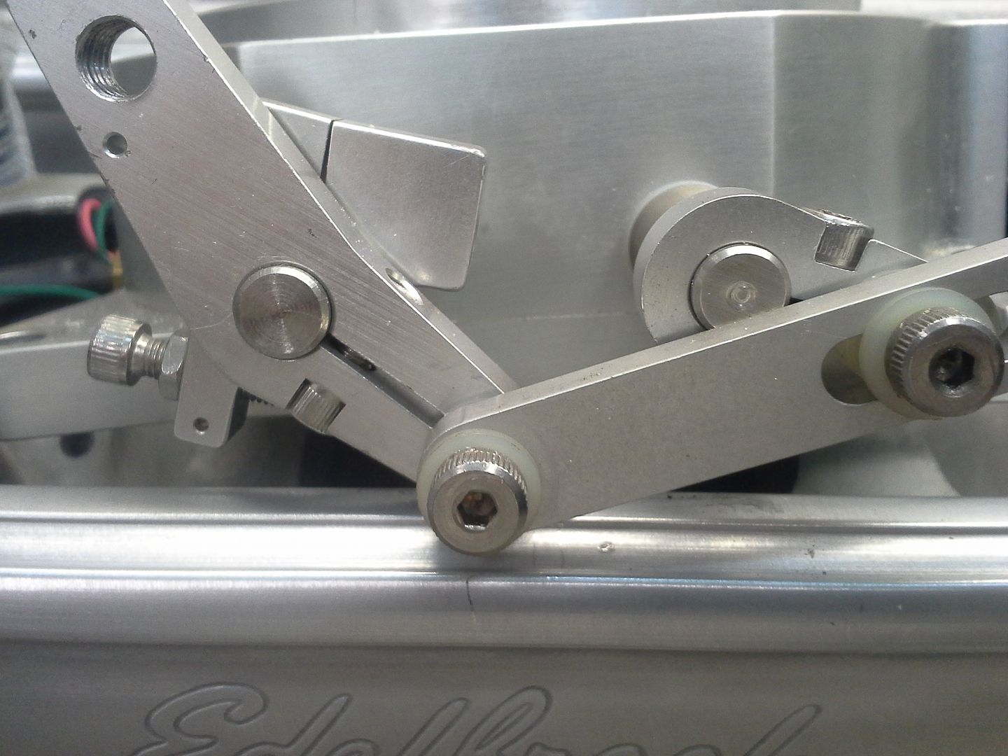
I got excited to see this setup this close. So I grabbed the 4bbl throttle body and the used 7727 ecm harness off the shelf and started a further mock up. The throttle body hits the fuel rails pretty badly. The harness needs altered significantly from its time powering a tuned port corvette. But it all will work together. A 2 inch open spacer will be used under the throttle body, which will allow it to clear the rails. Additionally, with the shorter throttle body and taller spacer, its still ½ inch shorter than the 950/1 inch spacer I ran on this manifold before. I can also drill and tap the spacer for my power brake/pcv ports, and my intake air temp sensor, thereby cleaning up the engine visually.


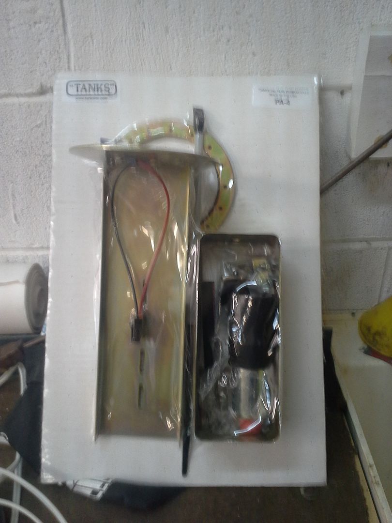
Nest up, I moved onto the fuel system for the efi conversion. Initially I had planned to use an in tank module from a late model gm product based on some write ups I found on the internet. Unfortunately, I couldn’t find a pump that would fit that would feed the small block in the duster. Rather than being faced with finishing another module and section of fuel tank to section in, I hit the easy button. I ordered the tanks inc pa-4 module with a walbro 255. 235 from summit, free shipping. I had debated between this and a surge tank/dual pump setup. I’m running that version on my elky, and have been impressed with its performance. However, I didn’t want to have fuel components inside the trunk of the car, and the pa-4 should clear the trunk floor with a couple of hammer whacks. So I went with the pa-4.


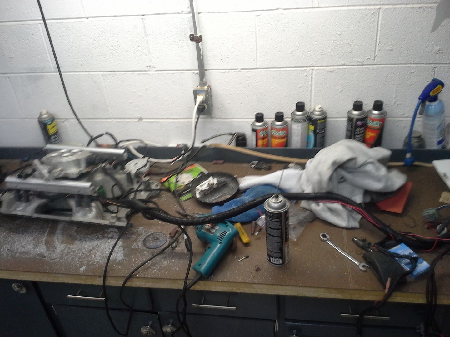
So this past weekend was the install time. I went down, and took some time out pictures. Here is where we started at. Car has not been moved, or touched, since april. Parts I started acquiring are in the trunk where they landed when they came in. new harness to replace the burned up one. New amp to replace the dead ones. Jump terminals. Etc. misc duster parts in a duster shaped storage box.


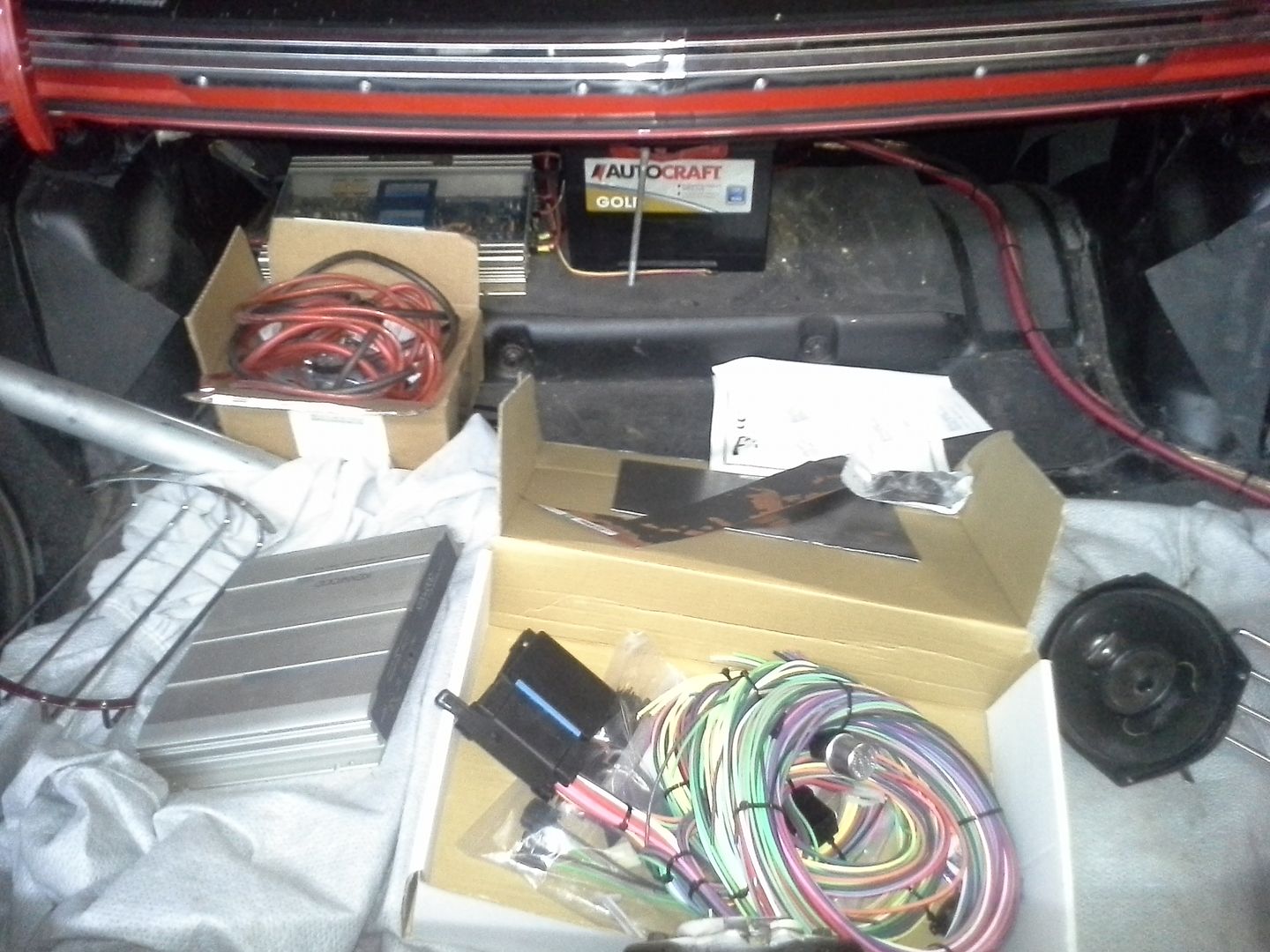
So Friday after work, I went down and got the car started. Fired up easier than it had any right to, but ran like crap. Eh. Don’t care. Its going efi. Drained the tank using the Holley pump (which I will NOT miss the noise of) and dropped the tank. Sat it outside to air out for a while.


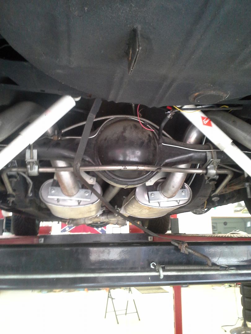
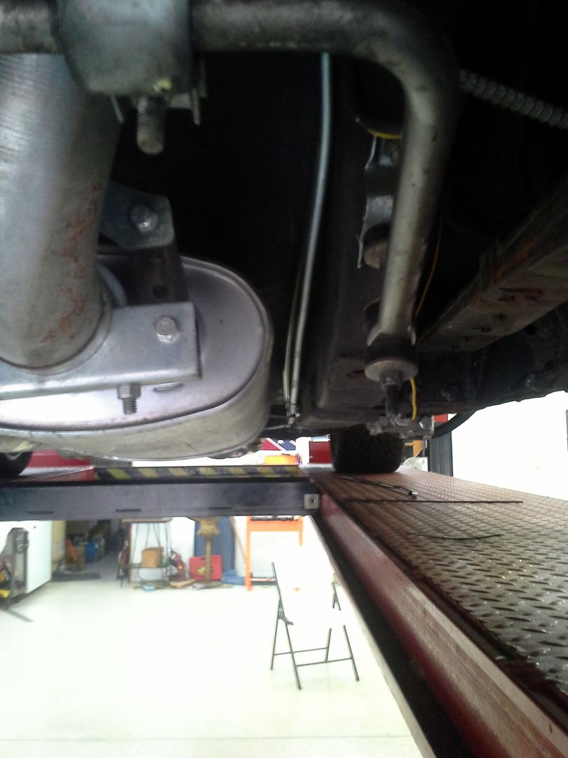
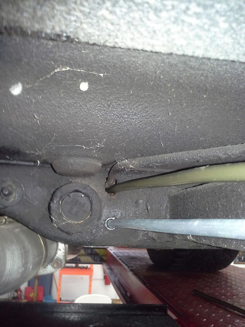
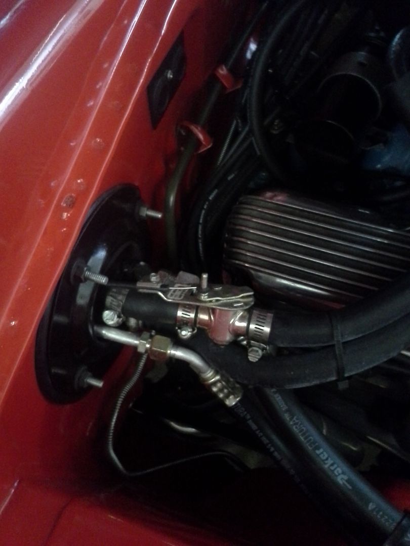
Proceeded to run the new feed and return lines. Decided on 3/8 for both to ensure an adequate safety margin for whatever I decide to do to the car later. Ran it along the sub frame connectors, through the t-bar cross member, and up the firewall, as well as into the trunk. Cut and flared the ends for AN flare nuts (had them). Green is pressure, and runs along the firewall to drivers side of the engine. Silver is return, and stops on the firewall near where the HVAC lines come out, as that is where I will mount the regulator. I made sure to route them in a way that in the event of a hard front end impact, they should not get severed. Fire bad.


I then moved on to the pa-4 install. This is where things get interesting.
I had to modify a gas tank full of extremely explosive gas fumes. Effectively, I’m adding heat and possible sparks to a giant bomb. Oh my.
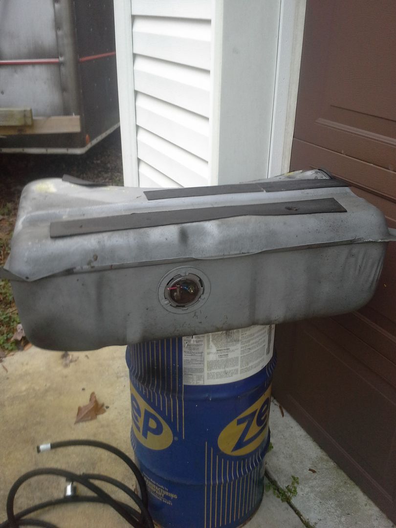
The safest way I could think of to do this was fill the tank with water. I put the fill tube in to make the water level higher, and proceeded to use a harbor freight 4.25 hole saw to cut into the tank. Worked well. Water came pouring out.

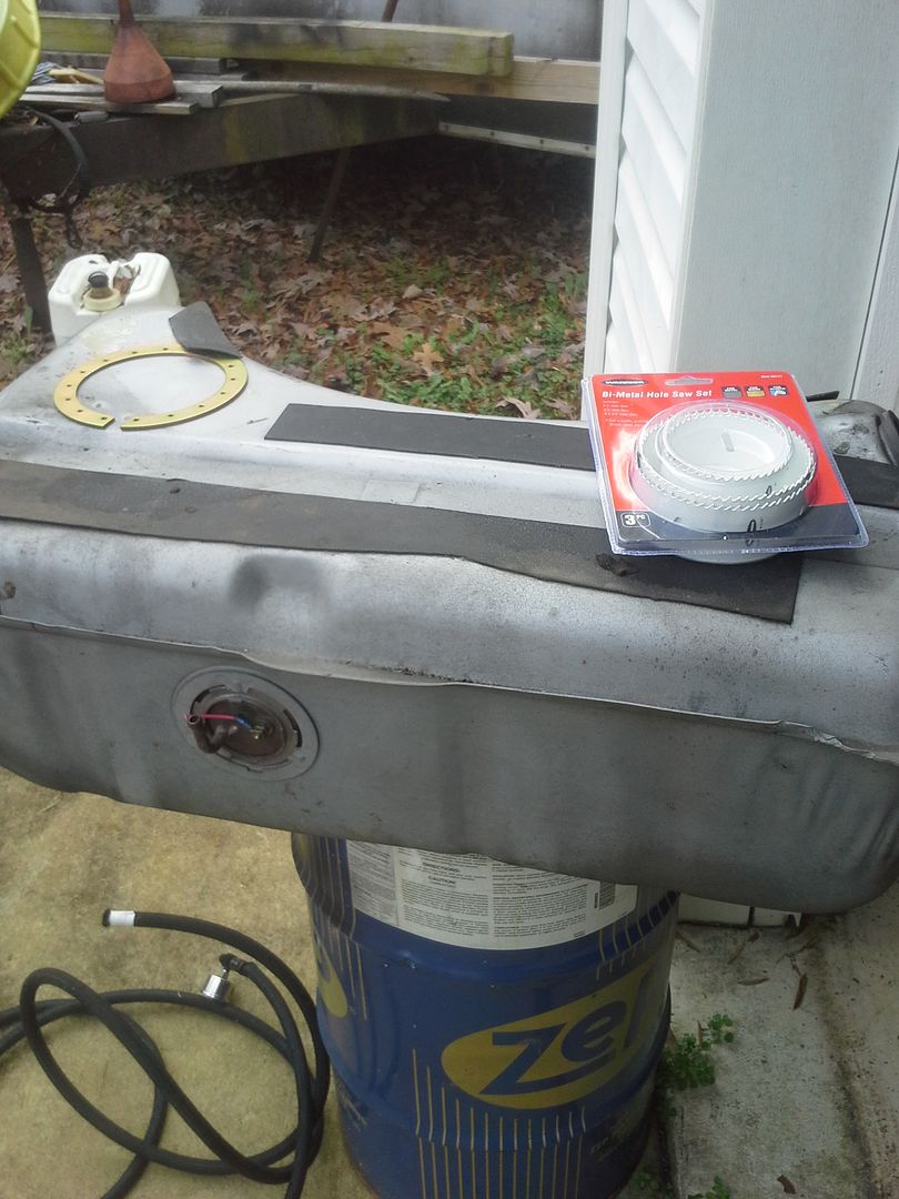
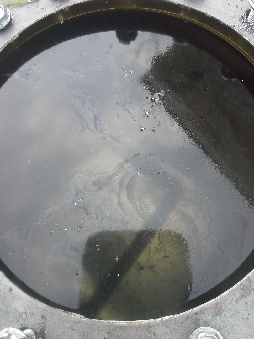
But at least the inside of my tank is squeaky clean. That makes me happy.

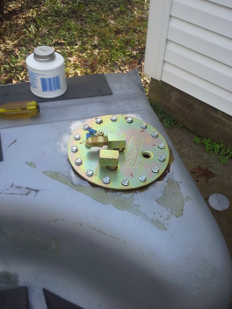
Got the mounting ring all set up, and decided that if I ever had to service the pump on the side of the road, life would be much better if the ring didn’t fall to the bottom of the tank. So best way to solve that would be to tack weld it in place.
It blew up. But only a little.


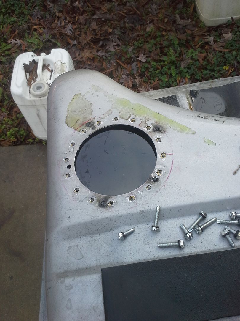
Apparently what had happened was there was an air pocket in the tank that wasn’t filled with water. It was filled with explosive gas fumes. When it went off, it blew half the tank of water out through the hole for the pump. Shot it high enough it was dripping off the roof of the garage. It scared me. A lot.
Anyway, I finished up the pump assembly.

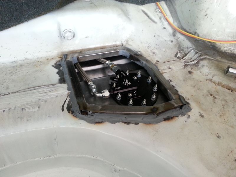
I then proceeded to go to mount it in the car. I thought I would have enough clearance to snake the lines out between the trunk floor and tank. Big old hairy no.
What I wound up with:

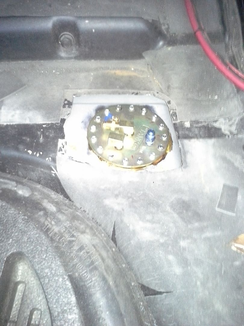
Ill make a cover that covers the pump assembly and seals it outside, as well as protects the lines. But the cover will be easily removable for side of the road service if ever necessary. The lines were rerouted to come into the trunk to hook up, and ill also mount a fuel filter in here. Guess I didn’t succeed in keeping fuel components out of the trunk after all…..

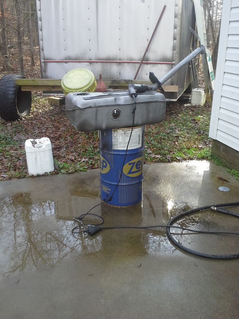
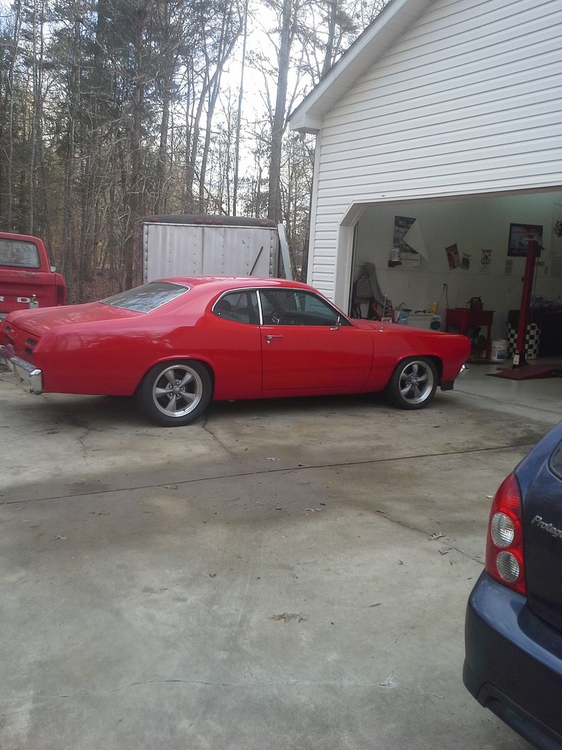
Anyway, filled back up with gas and hooked the carb system back up so I could drive it home. The gasket on the module is leaking, so I need to address that, and I also need to learn about tank venting and get that sorted out before hooking the whole efi system up.
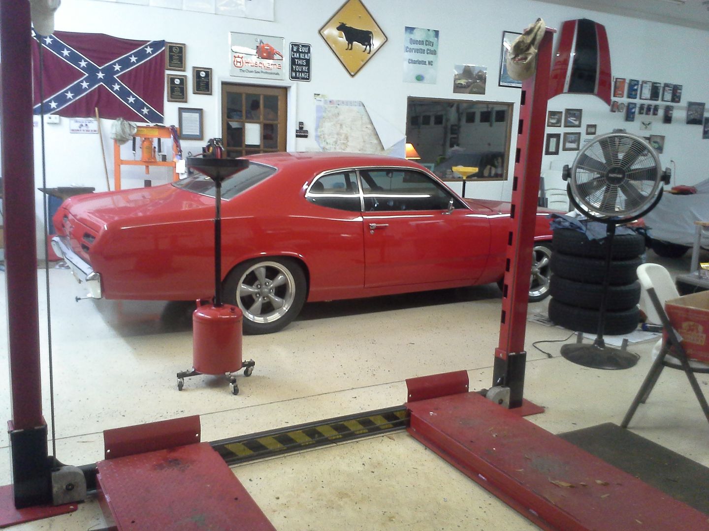
But she’s home. And on the road to recovery. Still have a few other projects to finish before I blow her apart to address the long list of issues, as well as go efi, but it’s near the top of the list.

Side note about budget line items: ecm is for the factory memcal so knock sensor and limp home will work. I lost mine. Polk and Memphis belle speakers, as well as amp, are for stereo upgrade. Jump terminals because I have a hard time reaching the battery being as fat and short as I am.
 
thanks guys. feels really good to be bak on this, even if its just a little right now. been ordering bits and pieces, and trying to get the manifold/injection buttoned up. ill do a full post when I get it all sorted out.
 
So, budget first:
Previous total: 8612.27

Parts bought:
2 inch spectre carb spacer, and edelbrock 6an fuel filter from amazon: 54.06
½ thick carb gasket, oreilleys, 7.99
6an-18npt adapters, eBay: 7.80
Injector rebuild kit, eBay: 19.25
5x 6an push lock, straight, eBay: 25.20
2x 6an push lock 90: 10.42
2x 6an/6an adapters, eBay: 3.98
1x 6an-1/4npt, eBay, 2.19
6 foot aeroquip socketless hose, free!
New total:
8743.16
Not too much of an update. Mostly just collecting parts. AN plumbing is expensive, but I think I have everything I need except for the fuel rail fittings now. Im also hoping I can clear the hood at this point….
The intake/throttle body/spacer/air cleaner stack is pretty tall. But it had to be to clear the rails with the linkage on the throttle body. Only other option is to try and modify the throttle body by removing springs and shortening shafts. Or, ditch the 4bbl throttle body all together, and run a 454 TBI setup with the injector pod removed. Supposedly flows about 780cfm that way. We’ll see what happens when it’s all bolted together.
I also need to make rail hold downs. I’ll do that in the near future after the intake is painted, and everything is put together with wiring, etc to see what I have to do to clear stuff.


Pictures of AN fittings:


Lastly, I rebuilt and cleaned the 30lb injectors, as well as did some math. These are rated at 30lb at 43.5lb of fuel pressure. At 60lb, they will flow 36lb, which should be enough for 400rwhp. In theory, at least.
So we went from this:

To this:

I think well be ok here. Worst case, I’ll pick up some newish 36lb injectors, and swap them out.

Lastly, I guess ill throw up a for sale ad here. I will no longer need the Holley blue pump, regulator, 750 edelbrock carb with electric choke, electronic ignition distributor, and pro-comp air gap intake. Figure a screaming deal at 300 plus shipping obo. If anyone is interested…..


Next up is painting the intake, modifying the spacer for some vacuum ports, mockup, etc. just chipping away at things.
 
previous total:8743.16

money spent:
iat/cts and various wiring connectors at pull-a-part: 21
correct 3/8npt to 6an fuel rail fittings: 25.91
6 feet 1x12ga steel: 14
new total: 8804.07

so ive been chipping away at this.

ive gotten the intake painted with por15 left over from the dual plane.


and I spent most of today making injector rail hold downs and a map sensor mount.


tomorrow will be making the fuel pressure regulator mount, coil bracket, and maybe drilling/tapping the carb spacer for the IAT and nipples for PCV and power brake vacuum lines.
 
I did the Aeromotive Phantom in the tank in basically the same place. Used some 3/4"x3/4" square tube with a cover to give clearance to hook up the PTFE hose. Once not in the relief cut, I dented the tank a little with a hammer to get it out to the front. Worked well.

IMG_20150919_124557_zpsqcwp1ujh.jpg
 
that is freaking genius!!!!

can I steal it???

Yes, of course you are welcome to copy. Take a measurement that 3/4" is enough for you. Mine is a pretty tight fit.

I welded the perimeter box outside the car, had to grind where the factory lap joint is, welded it in in a few spots and then seam-sealed all of it. Cover is held on with self-tapping screws.
 
Update time!

Previous budget: 8804.07

Money spent:

Misc brass fittings at lowes: 6.50ish

O2 sensor (4 wire), e coil, o2 sensor bung, and another set of gaskets 75

Sold intake, carb, distributor and fuel pump -350

Reman lean burn distributor 32

New total: 8567.57


So, I finally got around to the start of the major overhaul here.

But before that, I worked on finishing the intake up. Wanted to mount the fuel pressure regulator or the rail originally, but had decided that it wouldn't fit. Them I couldn't find anywhere else I wanted it. So I went back to the rail idea. Picked up some brass fittings from lowes, and here is where we wound up.


I then went to test this cheap ebay regulator. It leaked, both fuel and vacuum. Not good. Not good at all.

So I tore it apart, hoping it was something simple. It was. The Chinese kids that built it pinched the o-ring when they put it together. And left metal shavings throughout. So I cleaned it up, put in a new o-ring, and put it back together. Much success was had.


So, now ive got all the fab work done. In theory.


I was stoked. Moved onto distributor modification. All that I wanted to do was mount the ignition control module under the distributor where it would be nice and out of the way. So I used the infamous CAD (cardboard aided design) and made a bracket. Dissembled the lean burn unit I had picked up years ago, and cleaned it all up, etc.


It got scrapped for two reasons. 1, I lost one of the hold down clips for the cap over the years, and I was unable to locate a replacement. 2. There was no way to service the module once I installed the distributor in the car. 3. The hall effect sensor was fried. And then I dropped it. So.... I ordered a cardone reman unit from work. First one was bent. Second one works great!! I also wound up relocating the module to a piece of angle aluminum held down under one of the coil mount bolts.

So then a guy on craigslist actually showed up with cash for the intake setup. So we pulled the car out, pulled the hood, and removed it all.


Went ahead and drained the block as well, and installed the knock sensor in the passengers side water jacket plug hole.


I then went ahead and installed the efi intake, and plumbed it. Came out different than I expected, but it is satisfactory. I dig it.


At this point, I have fired it on ether, and started chasing lots of fuel leaks. Unfortunately, im now pulling the intake back off, as I lost a pintle cap down into the head. Better safe than sorry. Then, back onto fuel leaks. Im hoping to be able to test fire on full efi in the near future. Then, rewire and tuning!!
 
[ame="http://s54.photobucket.com/user/dusterbd13/media/duster/20160301_190639_zpsb1wjzbr4.mp4.html"]20160301_190639_zpsb1wjzbr4.mp4 Video by dusterbd13 | Photobucket@@AMEPARAM@@http://i54.photobucket.com/albums/g108/dusterbd13/duster/20160301_190639_zpsb1wjzbr4.mp4@@AMEPARAM@@54.photobucket.com/albums/g108/dusterbd13/duster/20160301_190639_zpsb1wjzbr4.mp4[/ame]
 
Budget first:

Previous total 8567.57

Parts:

Two -6 to 3/8 compression fittings: 29 from summit
Alternator from 89ish buick 3800 31 pull a part
Two new gates belts 22
Tuning from tpichips.com 250
Mr gasket throttle cable 21
5 relay panel, from britian via eBay, 41
12.5 ft of black, and 12.5 ft red 4 gauge cable, eBay, 21
Edelbrock steel carb “spacer” 20ish
Roll of cork gasket paper (had it)
42lb injectors, eBay 100

New total (ish. I'm having a hard time keeping up with the receipts at this point. Too much work, not enough organization) 9102.57

When I last updated, it was mostly sorta running. Not well, and not consistently, but running.

The first order of business was to get the fuel leaks stopped. There were a bunch of them. Compression fittings above the header. Flare from steel line to 6an male/male (both!). O rings on injectors slightly.

To fix the compression fittings, I just had to tighten them. The flares I cut off, and tried the earls compression to AN adapters from summit. These things were wonderful to work with. Very nice product. O rings were piddled with, then swapped out for 42lb ev1 style injectors. These are slightly shorter, which gives me the ability to lower my throttle body, and maybe fit the hood back on. They also don't leak, because they are running at 43.5psi vs the 65psi that I was running the 30lb injectors at. This engine made 390 at the rear wheels previously, which would pretty much max out 36lb injectors. Running the 30lb at 65psi, they were effectively 38lb injectors. Which were marginal. The 42s allow a little headroom (if I manage to make more power with the efi), and lower fuel pressure, which I deem safer.


Next up is a picture of the new mount for the ignition control module. Forgot to add a picture. Its a pretty simple piece of angle aluminum bolted to one of the old mounts for the stock coil. I have a heat sink from a vortec powered Chevy truck to add when I get to it, as these things get really hot and need all the help with cooling they can get.


With the fuel leaks stopped, it was time to add an 02 sensor. Drilled the driver side head pipe just behind the 3 bolt collector flange, and welded in a bung. No pictures. Ran it there so I can only have one wiring leg to the trans and 02 sensor, making a cleaner installation. Its also not in the collector due to the ceramic coating. Most recommendation are to put it in the collector so as to keep heat in it. I am running the heated sensor so I don't have to worry about it.

Then we moved onto coolant in preparation for tuning. Hooked bu the heater hoses, tightened, filled with water, etc. All ready to go.


Up next was the vacuum for the PCV and power brakes. These both have 3/8 line. I had no vacuum ports left. But I did have that nice 2 inch spacer, a rabbits foot, and no fear of failure.


Hit them with the drill press, a tap, and...


In the previous picture, you can kind of see the Mr gasket throttle cable. What a worthless piece of ****. It binds, the part in the kit don't fit one another out of the box, etc. Completely unusable. But I cut to fit and modified, and....

It still is unusable crap. I'm buying a lokar. Maybe then my throttle wont hang up.

I then had to mount my GM E coil. Wanted to mount it in the valley between the throttle body and distributor. You know, in all that wide open real estate I don't have. I bent a piece of aluminum, and did it though.


So with all that done, it was time to start getting it tuned. I had to get my laptop to talk to my chip burner, then talk to the ecm, then get tuner-pro to work, etc. I hate how complicated my new laptop and windows 10 has made all this. Wound up having to get a windows 10 compatible serial to USB adapter, and using a 10k resistor to get everything to working. The 10k resistor makes the ecm go into diagnostic mode, which jacks the IAC wide open, jacks timing, etc. Does some very funky things. I didn't know about that until I was trying to set IAC counts and idle speed. So I need to figure out how to access the ALDL stream without the 10k resistor. Anyway, while fighting with a high idle, I found an issue.


The scorch is from where it backfired. Through the IAC port. To OPEN AIR.

The IAC port was a giant vacuum leak. Apparently, this early Holley throttle body has a different design from the later in the IAC port, which makes the IAC port overhang a normal carb gasket by 3/8 of an inch. Massive, massive vacuum leak. Aint no way its going to idle or run properly. I managed to find an off the shelf solution though. The edelbrock sheet metal carb spacer/adapter thing.


It was within a couple of thousandths of covering the whole hole. I could see light through the crack when I shone a flashlight down the IAC port from the top, but only if I looked from the right angle. Close enough with a nice thick cork base plate gasket, as no off the shelf gasket exists that covers the IAC hole.


Now that that's done, we move on to something unrelated, but necessary.

I wanted a better accessory drive, with more fail safe, and more belt wrap.

So I started with a different alternator. The mounting lugs on the previous one were maybe 90 degrees apart, not 180 like mother mopar intended. It was also clocked wrong and dead. So, time to make it better. When I designed this accessory drive, I used a single belt to run the alternator, power steering pump, crank, and water pump. Also a belt from crank, water pump, air compressor. I wanted more of a fail safe. And the fact that I only got a roughly 1/4 wrap on the alternator/power steering pullies didn't help.

So, using a Buick 3800 alternator, with a 180 mounting design got me closer. At least better angles on the adjusters and mounts. But still not what I wanted. I wanted to be able to move the alternator in between the head and bracket and run a third belt. Started with re-clocking the case, which got me closer. The, broke out the dremel fro that last 1/8 of an inch.


Whee!!!

We then paid the tuner to send me a base map for me to try, and data log. Using Brian at www.TPIchips.com so far, hes been a pleasure to work with. He doesn't answer the phone, but is prompt with emails. Anyway, he sent me a base tune to try. First one was pretty rich still.


Second one got a whole lot better. Enough that I was able to move the car under its own power on EFI. I have no signal from the oxygen sensor, and need to work on tuning some more, then run it around the block a few times before I blow it apart for the wiring harness.

[ame="http://s54.photobucket.com/user/dusterbd13/media/duster/20160321_140642_zpslx8nx0a8.mp4.html"]20160321_140642_zpslx8nx0a8.mp4 Video by dusterbd13 | Photobucket@@AMEPARAM@@http://i54.photobucket.com/albums/g108/dusterbd13/duster/20160321_140642_zpslx8nx0a8.mp4@@AMEPARAM@@54.photobucket.com/albums/g108/dusterbd13/duster/20160321_140642_zpslx8nx0a8.mp4[/ame]
 
Alright, first things first. I need to get better with the budget....
I cant seem to keep track of what I spend lately. I know roughly, but need to get better about it.

Last budget: 9102.57

Money spent and made:

Sold the autometer gauges and adjustable shift light: -450
Bought a full on speedhut revolution package (they had a sale, and I'm a sucker...) 625ish
4 relay waterproof relay rack (80s GM) pull a part: 12
Electric antenna: 5.50
Experimental bilstien shocks:30
Sold 340 leaf springs: -100 and a set of sacked 4 leaf springs
LC1 wide-band 20
25 feet 6 gauge cable and terminals for alternator: 27
Rostra cruise control unit 75

That's the best I can remember....

New total: 9347.07ish

So, when we left off, I was having issues. It sorta ran, my laptop wouldn't connect properly to the ECM, the tune was wrong, and....

Well, I decided to start parting the car out while it was moved into the storage bay. I had a guy call me and ask me to build him a wiring harness. I had closed shop last year, and was no longer taking new customers. He convinced me. He also wanted a custom gauge cluster built just like mine. Now, one of the issues I had with my gauge cluster was that I found the white gauges tiring after a long drive. He didn't find the white gauges in his daily that way, and he loved the arctic white setup. So I sold him mine and ordered speedhuts. I love having warning lights, and with the small block mopar, and the EFI, there are just no extra ways without added complexity and failure points to do warning lights. Speedhuts have them built in. And they were black. And....

Anyway, I bought them, and started down the really steep part of the slippery slope.

Here they are in a quick duct tape mock-up:


And then I stuffed the thing back in the corner. And did thus:


i

In the process, I helped to design a new mopar product. Its a CNC aluminum bulkhead eliminator. Used the factory gasket, fits in the hole perfectly, and has a reinforcement plate on the outside. We actually made a run of them just like this, and if you want one, just ask. We haven't tested on anything but a-bodies yet, because That's all we own....


He also wants my leaf springs, so I sold them to him. I've been planning on building a custom pack with all the tricks I can throw at them, so this just spurred me on. Same with getting rid of the KYB shocks. To that end, I bought some used GM fitment bilstein shocks. The KYBs are up on the local craigslist, along with my big block torsion bars. That's all time for another post though.....

Anyway, the cuda left Saturday morning. Which meant than it was time for duster. But first I had to clean the shop. Which meant I had to move the duster. Spent the rest of the day trying to get it running again, culminating in letting the magic smoke out of the ECU and fouling another set of plugs. After picking tools and such up from the driveway (sort of lost my temper a bit...) I did some soul searching and talking with the wife. We decided that, as there is limited resources for the OBD1 GM ECM, and all the troubles I've had out of them in various uses over the years, and the incredible difficulty in tuning, and lack of tuners, to go megasquirt. So tomorrow, ill be ordering all the stuff for a full MS2 install.

Still didn't help the junkyard that my shop looked like. So I spent yesterday and today cleaning and reorganizing and moving the car. And helping dad replace a hot water heater in a crawlspace. That was fun....

As a point of reference, my wife and daughter got me the harbor freight wheel dollies for fathers day a few year ago. Last time I used them, I learned that the casters and ease of use left much to be desired. So before putting the duster on them, I re-greased all the bearings. They still suck. Once you adjust the direction of all 16 casters to point the direction you want to go with a 2x4 and hammer, its still a mother to push. On a clean, shiny floor. But we got it moved. And then cleaned. And cleaned. And...


I finished today by organizing all the parts that had been packed in the duster, removing the OBD1 harness and computer, and attempting to build a bi-xenon projector retrofit. Well, I built them, but I would have to cut clearance into the inner fenders for them to fit. Which makes it a no go, as it puts it directly into the path of water when in the rain. So, guess ill keep looking for reasonable priced alternatives. For now, the silver star sealed beams will stay, only with relays for added brightness.
 
Last budget: 9347.07ish
Money spent and made:

2 4 relay panels from Britain (why?) 52.40
25 foot 6 gauge alternator charge wire, and terminals: 28.90
2 add on relay blocks, and extra terminals 30.77
8 dodge neon 5 pin relays, pull-a-part: 24
Durango rear leafs, pull-a-part: 44
MS2, 10 foot harness, cables, etc from diyautotune: 740
Sheet metal from tractor supply 7:70
1/8 npt fuel rated schrader valve, diesel o-rings 5.50
Kenwood HD adapter and cable, GRM Forum member: 10


New total: 10,290.34ish

Ok, so I spent a bit of money.

More like a lot of freaking money. Holy crap, that escalated quickly.

Anyway, first, a very expensive picture. Ignore the LC1 in the picture, until I can test it good im not adding it.


And a picture of the schrader valve after a little explanation: I don't trust the mechanical pressure gauge. I've already had two fail, and if the Bordon tube fails, we get one heck of a BBQ going on. Id really rather not have that. So, this company I found, diesel o-rings.com, makes a 1/8 npt schrader valve adapter for some ford diesel to be able to use a normal fuel pressure tester on it. Which is perfect for my needs. I debated putting an electronic gauge in the car for constant monitoring, as well as a wide-band gauge and vacuum gauge.. I eventually think I probably decided not to add them. Because, lets be honest, do I really need them? If its running right, its running right. If its not, the gauges wont help me much. Just adds complexity, cost, and driver distraction. Which im trying to reduce here. A simple fuel pressure tester is fine for diagnostics and setting, as well as accurate enough. So, here's a blurry picture of a brass fitting sitting on my workbench.


So, now were on to wiring I guess. I have had people ask me to do a solid write-up of how to wire a car from scratch. Well, im not going to do that. There's books, websites, magazine articles, etc for that. What I will give here is some good tips and tricks that I have picked up after building over 30 wiring harnesses, as well as what products I tend to use and why.

First, lets talk about general planning.

This car will be fuel injected, air conditioned, cruise controlled, mid 90s level of technology, street car that will go on some tracks. So, to that end, some basic requirements are in order:
1. Ease of service.
2. Robustness.
3. Water-proof.
4. Future-proof

So, some of the things I will be talking about for my build are absolute, tee-total overkill. Like killing a fruit fly with an ICBM. Just fair warning: some of this would be ridiculous on another persons car. Hell, some of it is ridiculous on mine.

First, lets talk about battery. Mine is in the trunk, centered over the rear differential. It has a 0 gauge cable running from the positive side to the starter, and a remote kill in that cable. This is for ease of shut down, safety at the track, and ease of service on electrical should it become necessary on the side of the road at some point. For a remote kill to operate properly, it needs to shut ALL electrical down when flipped. This means that the alternator charge wiring and harness feed wiring need to be on opposite sides. Which means, by extension, that the alternator (at the front of the car) needs to go directly to battery positive terminal (at the back of the car). For this, I am using 6 gauge cable. Now, this is overkill for a 115 amp alternator. Its slightly large for a 140 amp (sometime soon), but is inexpensive in bulk. I use very finely stranded car audio amp power cable for this, as its very flexible, good bend radius, and cheap. The fine strands are the reason I up size slightly. I also use copper lugs when possible, crimping and dimpling them. I then use marine/adhesive heat shrink over the mechanical connection. The adhesive adds to waterproofing, and some mechanical pullout strength.


You'll also notice that I added convoluted tubing for the entirety. Id really rather not have a short in the alternator charge line due to abrasion, so I take every reasonable precaution when routing and then wrap it for another OCD layer of protection.

So, now we need to get the juice from the battery to the harness. On this car, im using 4 gauge amp wire from the battery kill, up the passengers side rocker, to the glove compartment. 4 gauge is way too much, really. But I had it. You will notice, again, wrapped in convoluted tubing for added protection.


The last battery connections are the basics of the ground system. In my experience, you can never have too many grounds. Also, the grounds can never bee too big. Even a ground wire carries current, so it needs to be the proper size or bigger to do its job properly. This car, I have a o gauge ground from battery to uni-body sub-frame in the rear. I have a 0 gauge from engine to front sub-frame, and a 4 gauge from battery to drivers side cylinder head. The 4 gauge is actually a little small for this, but I expect that it will NOT be taking much of the ground path amp load. Testing will prove/disprove this.

So, we've got a whole bunch of really big wires at this point, going to nothing. That's going to change in the next update, probably tomorrow night or the next night.


Last budget: 10290.34ish
Money spent and made:

Sold the 340 leaves -100
Sold the big block torsion bars -200
pst 1.08 tbars 230
Qa1 adjustable strut rods: 180
Spax adjustable shocks: 239
2 inch blocks: 20
Speedway leaf spring sliders: 69
4x4x6x1/4 leaf spring slider steel 18
Techflex f6 loom 50
Plugs/wires/cap/rotor 25
Spartan2 wideband and controller 100
Sweet mfg u joint 53


New total: 10,974.34 ish

Long time, no updates. But I have an EXCUSE this time!!!

But it a pretty lame excuse, so I wont use it.

I also don't have a bunch of pictures, because I honestly didn't take them. I got engrossed in building the harness, and just kept going. I find wiring to be very therapeutic and zen-like.

So, first up is the suspension tweaks. I honestly always felt the car was under-sprung and over-damped with the kyb’s, 340 leaves, big block torsion bars, etc. My steering coupler also needed rebuilt again, and my adjustable strut rods were seized sold and had to be cut out to remove. So yeah, pretty rough. I sold what I could, scrapped the rest. The t-bars went to California, the 340 leaves went to Roy in exchange for his worn out stockers, and the strut rods are in the scrap metal bin. The kybs are in cold storage helping to hold the floor down. Anybody want fairly fresh KYB shocks?

So up front, I replaced the chopped up strut rods with qa1 adjustable because they were inexpensive, looked to be well engineered, and readily repairable should the worst happen. Coated them up with never-seize because the ends are steel and the tube is aluminum, and I know there is some issues with that when you add water. I also went with PST torsion bars, and spax adjustable shocks.


In the rear, I wanted to try something completely lunatic fringe. Taking a page from the circle track/road race guys, I'm experimenting. I wanted to try my hand a a custom built leaf pack, as well as try out sliders. So I did.
I built, using Roy's worn out cuda springs and a set of junkyard durango springs, a 7 leaf pack with a spring on top of the main leaf to act as a traction/brake hop bar. They're right at 200 lb/in at the moment, so they may be too stuff. But with as simple as building the pack is, its easy to experiment with different leaves and lengths. The leaf pack I built wound up raising the car about 3 inches over where I had it on flipped hangars and 10 year old 340 leaves. I wanted about 1/2-1 inch higher, so we got too much. Grabbed a set of 2 inch lowering blocks at the parts store, and away I went!!


The sliders aren't finished yet, as I'm still arguing with the voices in my head about how to build the mounts. But I think I have a plan now. Maybe.
Here's the mock up.


Ok, next up I guess is going to be the very verbose, very dry, completely un-entertaining and baffling wall of text about wiring. Feel free to skip to the end, as there will be very few pictures worth looking at until then.

After building the main power distribution system in the last post consisting of ground wires, distribution panels, alternator wires, etc, we now have to put it to use. This is done with plenty of little wires of various colors going to various things. And so....

On most harnesses I have built for the old cars, I have come to the conclusion (right or wrong) that I don't want all the current going through the ignition switch. Mostly because they aren't rated for what the updates are pulling now (there's really no empirical data on amp ratings that I have found, but charging systems of the day were 75 at the HIGH end. Smallest alternator I have installed lately is 105 amp. So yeah, don't want that being sent through a Chinese copy of a 40 year old design...) so I relay the whole system. I use a panel that I found on eBay from Britain of all places, and only sent a 3 amp load through the switch itself. Use the switch to fire 4 relays accessory1 &2 (30a ea) starter (30a) and ignition (30a). I like doing it this way. I use Chrysler relays from wrecked 90s era FWD mopars, as they are robust, cheap, and over engineered. I use the Bosch 5 pin relay wiring diagram found almost anywhere. As my daughter would say, “easy peasey lemon squeezy!”. I also tend, on my own stuff, to use EZ wiring 21 circuit harness kits. They suck horribly. Poorly laid out, indecipherable writing without glasses, and slightly undersized in some circuits. Also, no ground wires, anywhere. At all. And if you're counting on the contents of the box to have all the terminals you'll need, you're wrong. American autowire is a much better product in every conceivable way, except price. I use these as the cheapest source of bulk colored wire and a fuse panel I can find. Immediately upon removing the harness from the box, I cut every zip tie and unloom it from the way the manufacturer laid it out. Out of 10 times I have installed one of these, only once was it anywhere close to how I wanted it laid out in the car. Its just easier to get the hassle of rerouting it all out of the way at the beginning.

So, in this car, I needed effectively two separate wiring harnesses. The main chassis harness, which powers everything but the EFI, and the EFI. I designed it in such as way that there are only 3 wires that cross between the two: batter feed to both sets of relays, one wire from the ignition relay to the megasquirt relays, and a ground screw for the relays. Everything else is separate. Relays also act as a filter for electrical noise, so using them is very beneficial. I also needed separate fuses for the injectors, megasquirt, fuel pump, and wideband. This whole fuse block is powered from the main relay, which is powered from the ignition relay.

Anyway, here's a picture of the panel I made for the glove compartment to hold all this crap.


Now comes the part that either makes or breaks the whole job. Routing the harness. It needs to be accessible, but tidy and hidden in plain sight. Its one of those jobs that when done well is not noticed, even though everyone can see it. Its very daunting. My method goes through a TON of zip ties. I tend to string one circuit at a time. Typically I start with the ignition switch and relay power. Now, I've done enough harnesses that I have a general idea of how big the bundles will be, and how they will need to be routed. I also, before starting to string wires, locate ALL electrical components where they will live permanently. Then, its just a matter of playing connect the dots. I also make certain to leave enough slack in my wiring drops to be able to easily service things later. It sucks digging around under a dash for the gauge cluster connectors because you didn't leave enough slack to fit your hand between the instrument panel and dash frame.

Which brings me to my next topic: harness connectors. In most cases, there is no good reason to permanently wire a component. Most things WILL fail on a long enough time line, and having to cut them out of the harness just to re-splice things is tedious and unnecessary. I tend to use a variety of connectors. My preferred are GM wetherpack, and radio shack 12 pin computer power terminals. They are readily available almost anywhere, easy to assemble and disassemble, and carry up to 15 amps reliably (you can do 30 amp loads, but the terminals are harder to find, and I prefer a Packard style for higher amp loads.)

Anyway, here's some random pictures I took.


On this car, I decided to install a rostra cruise control unit. But I didn't want anyone to know it. So I mounted it under the dash, feeding the cable out through the firewall with the wiring harness. Tucked up real nice, with nice cable routing. I also deleted all the extra wires that made it universal, just to clean things up. A lot of folks don't do that, and I understand why, but I'm not one of those folks.


Engine bays are where I take special pride. A well done harness isn't quite what the import kids used to call a wire tuck, but it kind of is. Its all hidden in plain sight. The type of wiring loom must coincide with the build style, the wires must be accessible but hidden, and they must be protected from damage. Factory usually wasn't the cleanest looking, but if you follow their suggestions, they'll get you pretty close. They did it for maximum ease of service and assembly. But also least succeptiable to damage.

On this car, I've had three different harness coverings on three different harnesses, factory was covered with convoluted tubing in high school. The last Restoration, it got wrapped with summit extreme tape, a non adhesive glossy black silicone tape. This time, I wanted something similar to the painless powerbraid. Techflex f6pro is on amazon for cheap, and I like it. Wrap the ends with the summit tape, and hide it in plain sight. See what I'm talking about? The entire engine bay is wired except plug wires in this picture. Play find the harness...


I also am a huge fan of light upgrades. I have a very hard time seeing at night, and old cars typically lack in the light department compared to new stuff anyway. So I build a set of bi-xenon projector retrofit headlights out of a jeep JK set of factory housings, and mirimoto 6.0 projectors. Unfortunately they looked like alien boobs, so I scrapped them and am throwing the projectors into the daily. Ill find a set of cibie e-codes and some good bulbs for this one.


On the topic of light upgrades, I do enjoy good interior lighting as well. Lately, I have been using these .96 cent 1x2 flat LED self adhesive panels for interior lights. They work well, though they don't always have consistent light color. This shipment was bluish. But, they are nearly invisible when placed properly. In this car, I've got two for trunk lights, and 4 for foot well lights in the interior. Speaking of interior, I finally adapted the neon hand brake lever, and dyed the console black. Only been meaning to do that for a couple of years. Additionally, I added a USB charge port to the console up near the cup holders. I still have to figure out how to hook up the parking brake handle to the rear drums, but, one step at a time.


Before we get to the gauge cluster, lets talk about the stereo. I wanted good front sound stage, decent bass, and high quality audio. So, to do this, I'm using a kenwood ez500 deck, with the HD radio add on module, some aftermarket power antenna, Memphis belle 6x9 3 way in the rear deck, blaupunkt 5.25 components in the kicks, some generic 4 inch speakers in the factory 4x10 opening in a plate made out of a mudflap, and a kenwood 3 channel amp powering the kicks and a first generation JL 12w6 wired to a 2 ohm load in a truck box. I need a bigger box for the sub, and possibly more power to push it. It ALMOST has the right amount of bass response.


Ok, if you haven't died of boredom or headed off to YouTube to watch cat videos, there's only two sections left.

First, gauge cluster. Remember I had sold the autometers and bought speedhuts? Yeah, they didn't fit. Not even close. So I wound up using the original metal pieces from Roy's cuda that held the lens to the bezel, modified for the speedhut gauges to sit in like gauge cups, glued to the back of the bezel with the gauges mounted. They are not serviceable without breakage. So hopefully they don't go bad. I then had to bore the center hole considerably to get the tach to mount anywhere close to where I wanted it, and make a lexan plat to hold it. Came out pretty good. Shot the whole bezel in black, re-installed my LED indicators, used a silver sharpie to color the letters for the switches, and jammed it home.


Last section I will be discussing my megasquirt experience up until this point. Now, mind you, I'm nowhere near a rocket surgeon. My computer skills are limited to word documents, Al gores internet, and listening to music. I can occasionally defrag a hard drive, and install a program, but I usually have to look up how to do it. I'm a borderline Luddite. I didn't grow up with computers, hate my smart phone, and believe skynet will be the death of us all when it gains sentience. But I have a small block mopar running on megasquirt. It still runs poorly, but dammit, it started up on the first spin of the key after adding gas to the tank and adjusting fuel pressure. So, if I can do it, anybody can.

Now, it isn't so intuitive as to be able to do it by myself. I'm just not that bright, nor is my reading comprehension involving computer things that great. The manuals are fantastic in guiding you through, once you figure out which manual you need, and read it about a dozen times. Then begin to follow the directions specific to your install. Realize you have no idea what the hell you are doing about the time you get to this picture:


Go back and read some more. Twice. Repeat as necessary until you have all the basic settings flashed to the megasquirt on the workbench, and tunerstudio responds appropriately to the jimstim.

Hook the ecu up in the car, make vroom noises while you play around making sure that sensor readings look reasonable. When they don't, research why. You probably missed switching a setting somewhere, and each setting has a domino effect on the rest. Again, repeat as necessary. After a while, turn the key and see what happens. Hopefully you get real vroom noises coming from the tailpipes, not your vocal cords. If not, keep digging around in the manuals and over at msextra.com forums.

I will also take this opportunity to say, without ANY reservation, to buy your stuff from diyautotune. Matt Kramer over there is the only reason I've gotten this far. He has held my hand and spoon fed me every step of the way. The forums at msextra and GRM have also been a huge help so far.

I haven't driven the car yet. Hell, I still haven't been able to set base timing or get it idling well yet. But I'm still learning this stuff. And if I can, through YouTube, email, and guys on forums, etc., anybody with 3 brain cells and a cup of coffee can. You just have to be patient and willing to learn.
 
-
Back
Top