Ammeter burnt out should I replace?

-

Dartalltheway

Well-Known Member
Joined
Aug 19, 2011
Messages
97
Reaction score
0
Location
Oregon
So my ammeter burnt out with a puff of smoke and I was wondering if I had to replace it or just bypass it? All help appreciated.
 
Frankly, I used to LOVE ammeters. I finally threw in the towel and did away with mine. Turns out it's easy to convert to a voltmeter, read this:

http://www.forabodiesonly.com/mopar/showthread.php?t=119480&highlight=ammeter+conversion

But be sure that IS the problem, as the top of the list (for trouble) seems to be the bulkhead connector. Also, it HAS happened that the molded wire ends at the ammeter have broken inside the plastic molding, AND the "in harness splice" can, has, and does fail. This is a welded splice in the black ammeter wire, a few inches down into the under--dash harness. It branches off and supplies headlights (only, not tail/ park), the fuse panel "hot" buss, the ignition switch main feed, and on some models, one or two other things.

My favorite article from MAD, good info. They have a simplified diagram down the page of the main feed system

http://www.madelectrical.com/electricaltech/amp-gauges.shtml

LOL, I was typing, Demon was postin'
 
I burned mine out because the battery was dead and I just jump started it and drove it home to charge the battery. The alternator was charging more amps than the ammeter could handle and it burned out. I bypassed it (put both connectors on one post of the meter) for a short time until I could find a used ammeter. There are many threads published here about this subject and rewiring the system to take care of problems. You can use the search function to find them. tmm
 
Happens to many people who upgrade their alternator to higher current. I did so in my Dart but installed diodes to bypass the ammeter as the current increases (see post). I am planning similar for my Valiant and bought different diodes to try with screw connections for easier installation.
 
Also a big problem that i ran into is that the ammeter guage itself shorts to the cluster housing by barely touching it. fixed it with a couple of strips of electrical tape.
 
Happens to many people who upgrade their alternator to higher current. I did so in my Dart but installed diodes to bypass the ammeter as the current increases (see post). I am planning similar for my Valiant and bought different diodes to try with screw connections for easier installation.

Do you mean the ammeter works as normal at low current, then bypasses as current increases? If so, can you direct me to that post? I'd like to do this.
 
I'd like to know what Bill Grissom is referring to by installing diodes to bypass the ammeter. Give us a diagram please. I'd also like to know the current capability of the diodes you use. I can't help but think you'd get a .7v drop across the diode.
 
I went to a voltmeter, but the idea of the diodes is that as the system charges harder there is a voltage drop through the harness/ ammeter. As the charging rate gets higher and higher (not just charging the battery, but the load by the accessories) this drop becomes enough to cause the diodes to conduct, which then act as a shut and reduce the current through the ammeter.

You could argue "why not just add a bigger external shunt?"

That was done in some installations, but the problem with a larger shunt (IE my Ferd Ranger) is it makes the entire scale of the ammeter a larger measurement. Example of my Ranger is, you get in, turn on the lights, and you ???maybe??? can see that the needle moves, not very useful.

A heavier copper/ etc shunt does the same thing -- makes the ammeter useless at lower amperage settings.

So the diodes, which have no voltage across them at low charging rates, don't affect the ammeter scale. It affectively changes the ammeter into an "auto ranging" scale, so to speak.

Wake up, Bill............................LOL
 
The old Mopar engineers, admitted many eons ago; that ammeter was stupid way to wire a car. Ditch it.
 
Link to my prior post
http://www.forabodiesonly.com/mopar/showthread.php?t=176755&highlight=Modernized

Since then, I found a maybe better part (MBRP400100CT, photo below), to use on my Valiant. Bigger than I expected. I will cut in two and bolt together flipped for a forward drop either charging or discharging the battery.

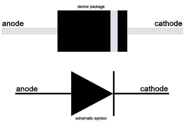
Re design, cudajim is correct that common silicon diodes have a nominal 0.7 V forward drop. Both diodes I used are Schottky types (less drop). Anyway, it is actually a curve that depends on current flow. Max is 0.7 V (@ 200 A) and dV decreases with temperature so kind of fail-safe. This matches what I measured I need. Read the post for more details. For some reason, the theory of i, dV, and R ticked off one reader. To specifically answer 4woody, the 2nd diode should give a 0.4 V min drop, so all alternator current should flow thru the ammeter at low currents (~1/3 scale). As alternator output increases, dV across your ammeter increases to ~0.7 V at full factory scale (~40 A), but you will never peg out because current will start flowing thru the diode bypass path. You would have to exceed 200 A to peg your ammeter. Show me that alternator.

Re installation. The diode pair is a new path from the alternator output stud to BATT+. Leave the existing wiring to your ammeter in place also. In my Dart, I ran across the SB timing cover, using a cable from a Magnum engine (as factory). Haven't decided the path in my slant. Most people could run a 6 awg wire to the starter relay big stud (BATT+). Either end is a suitable heat sink to bolt the diodes to (70 W max heat).I will use a modern relay box, as in my Dart.

Much mis-information on how your ammeter works. It is the only path to BATT+ from the dash, so all current flow into or out of the battery goes thru the ammeter. Under-hood loads like the starter, horn, and starter relay don't pass thru the ammeter, but they are transient loads so no need to meter. If your alternator is supplying all loads, you won't see any draw from the battery ("discharge" on ammeter).

I could sell these, but $13 for the diode pair, more for 6 awg cable, connectors, shipping, so probably $30 before any profit. Add in my labor, and little profit plus the grief/risk in dealing with angry, unskilled buyers. I would have to charge $100, and who would pay? For now, I give you the knowledge to make your own. That is much simpler than buggering with your ammeter in my opinion. Of course, also fix your bulkhead connector (as 67Dart273 laments) or you will smoke things even with the diode protection. Though, if you have a 65 like me, your bulkhead has the (apparently) 1-year only power feed-thrus (photo in prior post), so no melted bulkhead.
 

Attachments

  • 400A diode.JPG
    17.8 KB · Views: 2,379
The old Mopar engineers, admitted many eons ago; that ammeter was stupid way to wire a car. Ditch it.

What they said was "While this live indicater was a good thing on the assembly line, it proved to be problematic in the field".
Nobody ever needed to say, "I'm stoopid". Always plenty of finger pointers to say, "You're stoopid".
 
Actually I prefer ammeters IF they work without problems.. For one thing, if the battery is low, lights on, sitting long period, etc, the system can actually be charging but take a bit if the lights are on to bring the battery up enough to get "above the curve" and bring the voltage up. This means if you look at your voltmeter, it will be LOW and you might think there's a problem, when it's just trying to catch up.

But with an ammeter, you KNOW it's charging.
 
Wired an ammeter into a truck that I had years ago. As Del "sort of " states if they work properly they are a good thing to have.....Now the factory one....well that is a whole different story...
 
been stuck more times than i wanna think about becase that and aninetor so i got a floater up to 65 havent had a prob since just dont jump and bodies car or short anything out or you just fried it i lways carry 1 extra with me in both my 65 barracuda"s
 
A gauge is like a reporter. Both can be wrong, vague, or totally accurate, but never does a reporter step in and put an end to the subject of the report. An open shunt will stop your mopar. Clark Kent in the dash ROFL
 
Thanks for the clarification BillG, That is almost too easy!

I run original gauges in my 1938 Chrysler. Modern new wiring, and a 75 amp alt with electric fan & fuel pump, halogen lights etc; but I just love the look of the original gauges and I went through a lot to get them, & to get them working.

I was always a little nervous running the old amp gauge though, so I'll definitely do the bypass as you've outlined it.

One question: Diodes are directional aren't they? I don't know what the markings on the diodes in the pic above mean. Which diode above wires to the battery side, and which to the alt side?

Thanks again!

Here are the gauges I like so much:

Dash112.jpg
 
Diodes:

There are all kinds of diodes these days, from common rectifier to very fast switching diodes, and other stuff that is barely recognizable. But speaking in the general sense, in the symbols below, many diodes are marked with a band at one end. This is the cathode end, and can be best remembered by conforming to the "bar" in the diode symbol.

That symbol is evidently a carry over from early diodes IE "crystal radios" which used a chuck of galena or other material and had a "cat's whisker," a very fine wire used to probe the ore in order to find a "working" spot on the rock.

Accepted electron current flow is from NEG to POSitive, so current only goes through the diode AGAINST the arrow, or from cathode to anode.

(In the diagram, you would put the neg connection of the battery on the right hand end, and current would flow from right to left.)

If your reverse the polarity of the voltage against the diode it is said to be "Reverse biased" which for our purposes is a fancy word meaning "nothin' is happ'nin'

LED's (Light Emitting Diodes) are in fact diodes and are therefore polarity sensitive when operated on DC. If you hook them up backwards, they don't blow up, they simply don't conduct and therefore do not light.

diode+symbol.jpeg
 
So with the pictured pair what goes where?
Dumb it down for me: Battery wire goes where?, Alt wire where?
attachment.php
 
Either cut the device right in the middle or get different diodes which are separate. Bill did this because he thought they were good. I'm not sure in this case what you'd do for a heat sink, or if any is needed. Maybe Bill will get back in and clarify.

If you don't need a sink, you should be able to turn one upside down, and connect the tab out the end with one of the tapped screw holes on top, then do the same to the other hole. Your wiring would connect at each screw, at each side.

Basically, you run a second cable I'd guess about no10 from your alternator to the starter relay battery stud, WITH THESE IN series. If you look at the larger photo Bill posted, you can see the arrows.

When mounted, they would appear like this:

One end goes to the alternator output, the other end goes to the starter relay battery stud.
 

Attachments

  • diodes.jpg
    2.5 KB · Views: 2,217
Diodes:


(In the diagram, you would put the neg connection of the battery on the right hand end, and current would flow from right to left.)


This confused me. The shunt we are talking about is in the run from Alt to Battery + , right?
 
As 67Dart273 explained. Cut in two and nestle them so you bolt each outer hole to the tapped hole of the other. That puts them in "reversed-parallel" arrangement as shown and thus a forward diode drop for flow in either direction. You will need a longer screw than the ones it ships with. They fit together nicely.

Re installation, since the pair is symmetrical it doesn't matter which way you orient it. Put the diode pair in series with a wire from the big stud on the alternator to BATT+. You also leave the factory wiring in place (which runs thru the ammeter to get to BATT+). Doesn't matter whether you attach it at the alternator side or the battery side, but you do want a good heat sink. If you can't calculate the power dissipated (P = i * dV) and have a feel for that, you probably shouldn't be doing this. Also, don't leave any metal exposed or your first wrench drop on it will prove that you can weld with a car battery. Wrap with heat shrink or self-fusing electrical tape, not the cheap vinyl tape that falls off in a month and looks hill-billy.

In all Darts, you can get to BATT+ at the big stud on the starter relay. Well, not on mine since I removed the factory one and use a relay in my modern relay box. In a small block, the most direct path is a new run across the timing cover, as is done in Magnum engines. That is what I did, indeed using a factory cable from an 80's Dodge truck (or Jeep). It looks like ~6 awg but you might go smaller (8 or 10 awg), depending on the alternator you have. In my Dart & Valiant, I put (will put) a Battery Brain next to my battery and bolt the diodes there since easy and a sufficient heat sink with all the thick copper wire.

Finally, for the theorists reading, why do you need a diode in both directions since the alternator only puts out current? Because the bypass diodes aren't for the alternator, but to protect your ammeter. Your ammeter is in series with BATT+ and current can flow both in (charging) or out (discharging) of the battery. You don't want to peg your ammeter from a large in-cabin load. However, if you can limit those by supplying any large loads (power seats, monster amp) direct (before ammeter), you might get by with a single diode just to limit charging currents. I didn't since almost as easy to protect both ways. I'll repeat that the ammeter does not meter most under-hood loads (starter or horn) so people don't call me an idiot (though often am).
 
Originally Posted by 67Dart273
Diodes:


(In the diagram, you would put the neg connection of the battery on the right hand end, and current would flow from right to left.)


This confused me. The shunt we are talking about is in the run from Alt to Battery + , right?

See Bill's post above. the diagram I referred to with that comment was only an explanation of a SINGLE diode operation. You will have TWO diodes, and current will flow in BOTH directions When you get the two bolted together, you will have the equivalent to the second diagram I posted:

attachment.php
 
Thank you both for the additional explanation. I just wanted to be sure I understood what you were saying.

Bills final paragraph above also reminded me to double check where I'm getting power for the electric fan & fuel pump.
I rewired it completely 5 years ago and no longer remember exactly how I did everything, but I'm wondering if those items- though "Under hood" shouldn't go through the ammeter?
 
-
Back
Top