I've been grappling with a charging problem on my 1968 Barracuda notchback, 340 six-barrel. I thought it might be the voltage regulator, because testing showed it was not keeping up enough power. I replaced it. I eliminated the battery or alternator as the cause.
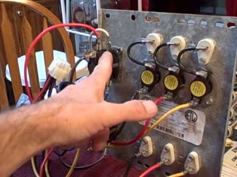
Now I believe the weak charging is a result of corrosion on bulkhead wire terminals. I am having difficulty removing the terminals from the bulkhead so I can replace them. I've use a needle nose pliers on the males. No use.. Suggestions?
There has been hundreds of threads on this. No, I'm not kidding.
Here's an excellent starting place:
http://www.madelectrical.com/electricaltech/amp-gauges.shtml
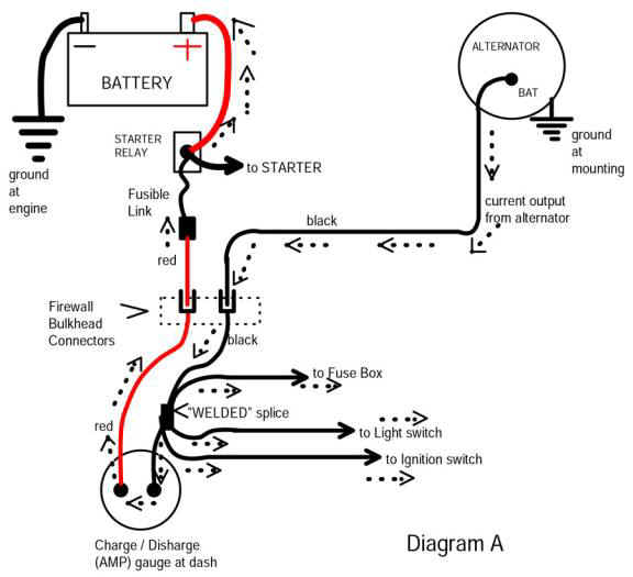
Here's the simplified diagram on that page
I take these problems as a "total package" but I divide the problem into sections
Generally this amounts to...........
1...Individual components, alternator, VR, battery
2...The output circuit of the alternator, or "charging line" that part going from the output stud, through the bulkhead, ammeter, back out the bulkhead, fuse link, to battery
3...The Field / VR part of the circuit. This is where the bulk of OVER charging comes from because you can have VOLTAGE DROP in the harness. The "path" and the main points of trouble are:
From battery, through fuse link..........through bulkhead (red wire)..........to and through ammeter..........welded splice..........back out bulkhead (black wire)........back to ammeter
The path to the VR is Battery........fuse link........through bulkhead (red)......to and through ammeter......(black)......through welded splice..........to ignition switch connector, through switch and back out switch connector.........(on blue IGN 1 wire)........back through bulkhead..........and feeding VR, ignition loads
THIS LAST above is very troublesome. You typically develop bad connections in all of those points, the bulkhead connector, the ignition switch connector or switch, and SOMEtimes the welded splice!!!!
What this does is create a VOLTAGE DROP which feeds lower voltage to the VR. The VR "thinks" the voltage is low and so cranks it up. It starts to maintain 14V at the VR sense point, but because of the drop, the battery now becomes HIGH -------by the amount of this drop
==================
To test for ignition harness voltage drop, get your meter "clipped" to as close as you can to the VR IGN terminal. This might be the ballast, the closest you can get. With the key in run but with engine stopped, find the highest voltage at the ballast. Now move your ground meter probe to the battery POSitive post, on low DC volts. You are hoping for a very low reading, the lower the better. If this reading is more than .3V (3/10 of one volt) you have troubles in the harness
================
The GROUND circuit can do the same thing but more rare. The VR MUST be grounded to the same potential (voltage) as the battery ground.
you can test the ground in a similar manner. Get the engine running fast idle, battery warm and "normalized." "Stab" one probe of your meter onto the metal flange of the VR. Be sure to stab through paint, etc. Stab the other probe onto the battery NEG post. As the test above, you are hoping for a very low reading, zero would be perfect. Make the test with all accessories off, and again with lights, heater, etc, turned on. As with above more than .2--.3V is too much.

")


