I went to the full GM TBI system, with computer controlled HEI, heated O2, Knock sensor, speed sensor, and electric cooling fan on a 65 2 barrel 273
Have you done a write up on this, because I KNOW there's some of us "want to know"
I went to the full GM TBI system, with computer controlled HEI, heated O2, Knock sensor, speed sensor, and electric cooling fan on a 65 2 barrel 273
")
Nope, I picked up a E-core Coil.
Sweet, you are going to like how it starts and runs.
Don't forget to regap the plugs to at least .045
Using the GM HEI module outside of it's dizzy, just bolted to a fender liner or what-not, had always bugged me from a corrosion potential position. Here on the Coastal Desert I've got to consider such things. One could argue that the GM dizzy isn't a sealed container for the module and I'd agree, but it must be good enough elemental shielding because corrosion isn't a usual complaint.
I'm liking this mod because it provides about the same amount of shielding from the elements as a GM dizzy does, maybe more and it's cool because it's not what people who see it think it is. Years ago (~1988 ) I put a Toyota EI module in one of those old 70's era aftermarket CD Ignition housings and converted the dizzy to the Toyota inductive pick-up too. Looked like an old points driven CD ignition, but was something far better.
As to the TBI wiring, there are many, many wiring diagrams out there suitable for the conversion. The 7747 ECU is the most common and pretty much the only ECU used in swaps. A simple search on the topic will turn up more info than is useful. I have the complete system from a 2.8L GM V6 that I'm working towards installing on my 170ci (2.8L) slant. The biggest issue for me is that I don't want the ECU to have control of the timing at first. So how to send the RPM signal to the ECU w/o also allowing timing control or altering the loom is a dilemma that I've got to solve. Eventually the ECU will have timing control (doing one step at a time), so altering the loom isn't very desirable.
Attached is one such diagram that I found on an I-H site where TBI conversions appear to be quite common.
EDIT: Just now looking at the attached diagram I see the solution to my timing control situation.
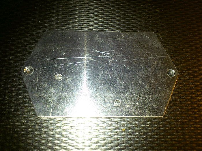
I became fed up to wait for my boss make the bracket. So I did plan B and made a plate like 360duster. 360duster your plate looks to be laser cut? It looks good.
Next thing is to paint the casing black.
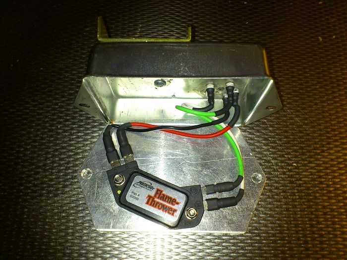
The OEM housing has a heat sink on the top. Yeah its kinda primitive in design but since it is there... Why not take advantage ? There's a couple ways to get the heat from the bottom of the GM module into that heat sink. Maybe its not worth the effort.
Time will tell.
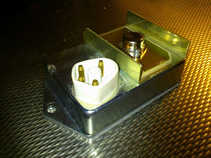
That shallow aluminum channel piece, usually clear or gold anodized, is a heat sink for that exposed device (transistor?) in the middle of it.The OEM mopar housing? where?
That shallow aluminum channel piece, usually clear or gold anodized, is a heat sink for that exposed device (transistor?) in the middle of it.
Has anyone seen this yet?
PerTronix to Feature its New Flame-Thrower HEI III Module at SEMA
Flame-Thrower® HEI III 4-Pin Module
Available for all popular GM applications, the new Flame-Thrower GM HEI III 4-Pin Module features multiple sparks through the entire rpm range and includes an integrated digital REV limiter with LED feedback for precise RPM setting. Fool-proof control eliminates engine damage when rpm goes out of control from a missed shift or excessive wheel spin.
Thanks for the tip on the flame-thrower, I have been looking for an economical rev limiter to put on my kids first car.


Why not just clear bore the top one and tap the bottom one ? Chamfer the edges, check flat. Another dose of compound between the two will do the rest.
#6-40 will give you 5 threads in a eighth. I guess that would require shoulder screws.
2 pieces tapped causes a jamb nut effect in the threads when tightening.
so you think that tapping the 1/8 will be enough? If so, i have the original small bolts that held the HEI module onto the GM distributor, do you know what tap to get to use these original bolts?


