72ScampTramp
Scamp Tramp
Trying to get educated on sub frame connectors for my 72 scamp. Id like to see photos of different styles. Also what size and style of steel are you using?


alright so the best way to do it is with the motor tranny and rear end out. thats easy enough since there all not getting used. So 3x2 with .120 wall.
")
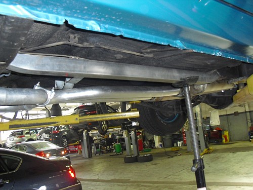
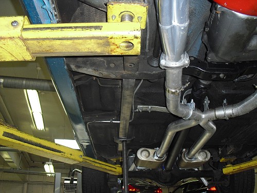
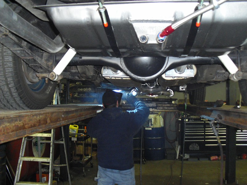
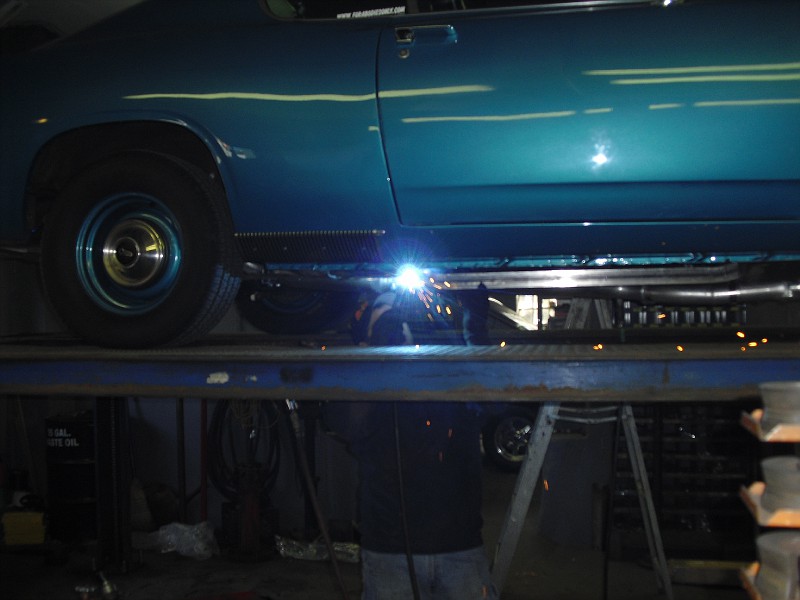
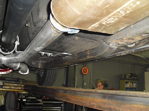
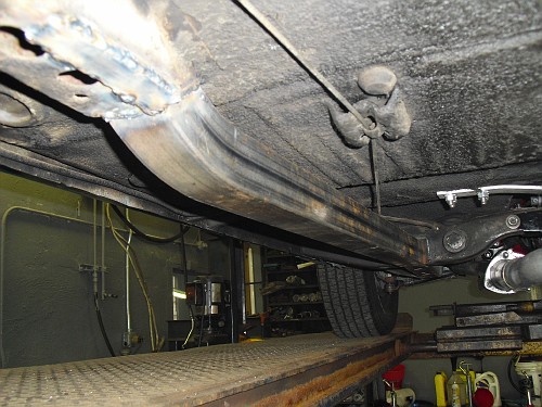
Does anyone know if 2x2 tubing or 3x2 with the 2" side vertical would be tall enough to contact the bottom of the pan? I was thinking about connectors but i didn't want to cut up the floors, and i figured that welding to the bottom of the floor pan would be better than not touching the pan at all


