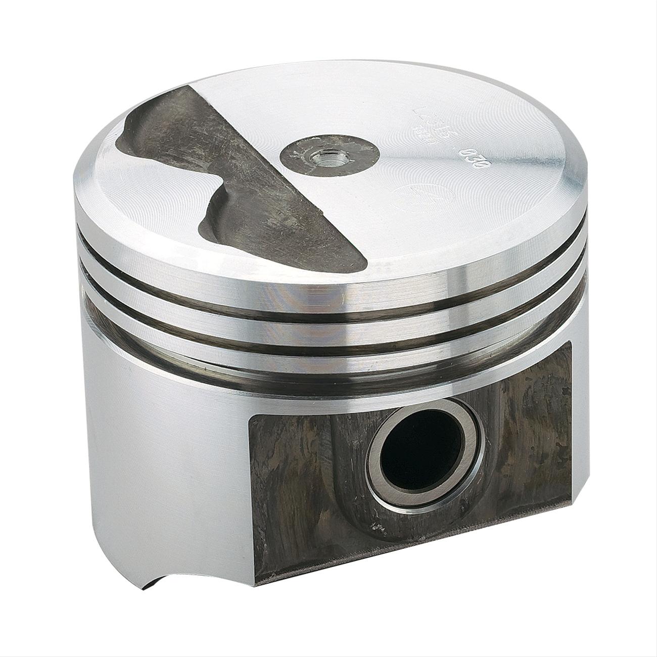
Was able to measure pistons #1,7,2,8 for height proud of the deck.
In my other thread I only measured 1 and got .034". Not sure if either time was more accurate than the other. Not too concerned as I'm not trying to squeeze anything drastic out of it.
Both #1 and #7 were 0.027" proud of block, #2 was 0.028" and #8 was 0.030"
I'll use 0.030" for calls to be on the safe side.
Installed cam and oil pump drive. Used wrench a bolt and washers to balance cam while installing.
Soaking the chain for new JP tc gearset.
While digging for fuel pump eccentric I noticed I'm shy a cam plate and bolt with hole.

I'll be posting a want ad for that...
Have to go thru new M72 oil pump and install MP spring kit.
View attachment 1716018917
View attachment 1716018918
View attachment 1716018919
View attachment 1716018920