Sub-frame connectors... Please build them correctly!

-
I'll weld the doors closed and solid all around to see what difference that makes. May not need subframe connectors at all. LOL

You've been watching to many episodes of Dukes! :)

Of having one too many beers with Greg
 
What is interesting to me here, is the amount of people saying that there is so much flex in these cars. Its obviously a known problem, but to notice a difference from just the little bit of added strength from the floating type of connectors is pretty crazy.
*Thats not sarcasm or disbelief. Its truly crazy that they flex so damn much.

Seems that most people saying that have hardtops...and I'm not surprised. That is a BIG door opening with no bracing except the rocker & roof!
 
I have to say.... All the input here has been valid. None of it....none... has fallen on deaf ears with me.
According to my stress analysis the attachment to the floor has a difference of around 30% in favor of welding to the floor pans. Now of course there are many more factors that would require me to reverse engineer the entire uni body structure in order to prove the point with out a doubt, but you all get 're point based on the items shown.
I cant rightly show a decent result of the stress in stock form because of the amount of reverse engineering involved.
Anyhow... all that said... IF...........you do a few key things .....namely spread out the force from your tubing to the sub frames by making as much contact as possible you will greatly increase the strength of even the floating style connector.

Im glad that you all step up to throw in your two cents as this is also the way I do things daily at work. I like to hear input from everyone, no matte let who they are and what position they hold because you never know who is thinking od something you are not!
thanks guys...
Bottom line... as the stress analysis shows... Its better to attach it to the floor. ;)
 
I was at John's (US Cartool) shop a few years back and he showed me a Dart/Valiant they had welded 2 sets of floor pans in. He had some interesting numbers from before/after twist on that one........
 
My opinion?? The OP is stating the obvious, anytime you can add structural rigidity, it will significantly reduce flex! These cars were traditionally "thrown" together, and can all stand to be completely gone through and stiffened through welding, even most of the already welded components! Is a spot weld every 4" better than one continuous seam weld? Of course not! Why did they take a little extra time welding the 340 K frames? How bout the torque boxes on Hemi, 6pak and convertible cars? Because just a flat floorpan with some stamped rigid gusseting is obviously "just enough"!!

I agree, weld the heck out of everything, and add the top flange to 2x3 tubing like the factory frame rails too while you're at it!! Good info included in this thread! Geof
 
I turned my US Tool contoured frame rail connectors into scrap metal. They didn't line up to the contours of the floor pans for **** and the amount of work it was taking just to get them installed wasn't worth my time or headaches....put on a set of Mopar Performance connectors in an hour and voila. My wifes cuda convertible....used to flex in the middle when you put it on a lift. So bad that you had to have the top up and latched cause the door gaps got scary wide. Now it doesn't flex at all when it's on the lift and it feels like a different car on the road.

No matter what you use for rail connectors, it's a huge improvement over stock (none).

Just cause someone thinks one way is better doesn't mean it's so....regardless of all the graphs and pie charts and cool graphics. That's why there is more than one way to do this.

Hell you could put the body on a Ford truck frame and get the most flex free vehicle on the road. :)
 
I was at John's (US Cartool) shop a few years back and he showed me a Dart/Valiant they had welded 2 sets of floor pans in. He had some interesting numbers from before/after twist on that one........

I have known John for about 8 years now. The guy legitimately is at the genius level, not just in the mopar world but truly that intelligent. For $600 your mopar chassis will be as stiff as it can possibly be:

http://store.uscartool.com/a-body-chassis-stiffening-kit.html
 
Idk if anyone has mentioned this, but some road racing and autocrossing classes state that your subframe connectors cannot be attached to the floor board or else you're going up in a class.
 
Yup Yup Yup,
I have a 69' Cuda I built back in the 80's with a 440, this was before the mega information age and instant information access and I was also in my 20's. It had no subframe connectors and with slicks I started to see this drivers side rear roofline crease develop and get worse the more I raced. That's when I learned about subframe connectors and I ordered some bolt ins from Direct Connection followed the instructions (I think, lol) and drilled some holes, bolted them in and Bingo the roof creasing stopped, my 60' improved and the car stayed straighter when hazing the tires. THESE WERE NOT WELDED IN and they obviously made a difference. I certainly agree welded in and tied would be better sooooooo guess I will do that. Mopar packrat that I am I still have this Cuda but many others have joined my Plymouth portfolio (hahaha) since and the 69 just sits tucked away for now as my backhalved 64' Valiant is a better track setup. Interesting and informative thread but my personal experience with non welded and tied connectors kinda disproves your stated fact that it was a pointless endeavor. It's all good bro!
 
Most of what has been stated in the thread so far is pseudo-engineering. Sorry, it is. The computer "analysis" that was done is next to useless. It doesn't even come close to modeling any of these cars, and makes assumptions that you have no way of justifying. The idea that parallel members don't carry a load is completely false. Take a look at a truss style bridge sometime. If you took out all the parallel members you wouldn't even have a structure anymore. These cars themselves have multiple areas of parallel structural members.

The biggest issue with your "analysis" on non-welded subframe connectors is that you're only testing a single loading point. Obviously, these cars can be loaded from ANY point, and not just with a single input. You'd have to do a full analysis with regard to bending AND twisting, which isn't what you've done. Not to mention the additional structural members, the stiffening effects of the formed sheet metal in the floor, etc.

Welding to the floor isn't necessarily the best way to install frame connectors. Is it as strong? It can be. But keep in mind you're welding together two different thickness's of metal, which creates stress issues. Not to mention that all of those will probably be MIG welded, so you have a somewhat brittle weld connecting a heavy gauge metal to sheet metal, which will still flex, and could cause cracks along the edges of the weld. Not to mention the difficulty in cleaning the chassis and welding the entire length of the connector. If this isn't done on a fully blasted car on a rotisserie, the welding will be less perfect, which will reduce performance.

Welding in a tubular frame connector that doesn't attach to the floor can be just as strong. It does depend on the cross sectional area of the tube, and the thickness of the wall, but it can be equally as strong. It's not a perfect solution either, you can still have stress issues if you're welding a really thick wall tube to the frame, so larger landing plates than most people tend to use would be better. But you can weld them in on a completed car, it's much simpler to weld them in if the car isn't on a rotisserie, and they can be home fabricated. Are the home fabbed one's as strong as they could be? Probably not, because everyone makes compromises. Thinner or thicker wall, smaller cross sectional area to clear certain structures, etc.

I don't think that there's a "BEST" way to do the frame connectors. The laser cut subframe connectors certainly look more factory, and I think they do an excellent job of stiffening the frame. But so do tubular frame connectors, especially if they're done with larger landing plates. Both versions will significantly stiffen the car, which I can attest to since I have actually installed a set of tubular frame connectors on my Duster. The difference is night and day.

The "best" way to add a subframe connector is the way that you're set up to do it. If the car is on a rotisserie and has been blasted and cleaned and you want to retain a factory look, the laser cut connectors are the way to go. If you're doing this at home on a completed car, don't have access to a rotisserie, or aren't skilled in welding heavy gauge metal to sheet metal, the laser cut connectors probably aren't the best for you. Same if you're racing, because a lot of sanctioning bodies will put you in a different class if your connectors are welded to the floor. You can build tubular frame connectors that will work just as well or better than the laser cut ones, it just depends on how you do it.

You can build a tubular frame connector that is stronger than the weld to the floor kind. And even the weld to the floor design can probably be made stronger than the US Cartool ones that everyone uses. But you'd have to do a structural analysis on the entire chassis to know which one was actually better, and NO ONE has done that. Bottom line is, either method is light years better than doing nothing. And unless you're racing the car on the track or road, either method will more than suffice. And if you are seriously racing your car on the track or road, then you'll probably need a full cage anyway, and the method of installation will be dictated by the sanctioning body you race with, so that will be your deciding factor.

And yes, I do hold an engineering degree. I have a bachelor's in Aerospace engineering, with my major focus being in structures, although that's not what I do for a living. My take on subframe connectors is here http://www.forabodiesonly.com/mopar/showpost.php?p=1970045503&postcount=39. And I fully admit this is not the absolute "best" or "strongest" way to make a set. But it accomplished what I wanted to accomplish, and I can tell you the result is a car that is significantly stiffer than it used to be. I also have a set of US Cartool connectors for another one of my projects.
 
And yes, I do hold an engineering degree. I have a bachelor's in Aerospace engineering, with my major focus being in structures.

Well whatever you do, don't post your own drawing or I'll throw it off into the Grand Canyon as well. :D

You know I am just kiddin ya just like I was with the OP.
 

Attachments

  • grand-canyon-size.jpg
    33.7 KB · Views: 811
Most of what has been stated in the thread so far is pseudo-engineering. Sorry, it is. The computer "analysis" that was done is next to useless. It doesn't even come close to modeling any of these cars, and makes assumptions that you have no way of justifying. The idea that parallel members don't carry a load is completely false. Take a look at a truss style bridge sometime. If you took out all the parallel members you wouldn't even have a structure anymore. These cars themselves have multiple areas of parallel structural members.

The biggest issue with your "analysis" on non-welded subframe connectors is that you're only testing a single loading point. Obviously, these cars can be loaded from ANY point, and not just with a single input. You'd have to do a full analysis with regard to bending AND twisting, which isn't what you've done. Not to mention the additional structural members, the stiffening effects of the formed sheet metal in the floor, etc.

Welding to the floor isn't necessarily the best way to install frame connectors. Is it as strong? It can be. But keep in mind you're welding together two different thickness's of metal, which creates stress issues. Not to mention that all of those will probably be MIG welded, so you have a somewhat brittle weld connecting a heavy gauge metal to sheet metal, which will still flex, and could cause cracks along the edges of the weld. Not to mention the difficulty in cleaning the chassis and welding the entire length of the connector. If this isn't done on a fully blasted car on a rotisserie, the welding will be less perfect, which will reduce performance.

Welding in a tubular frame connector that doesn't attach to the floor can be just as strong. It does depend on the cross sectional area of the tube, and the thickness of the wall, but it can be equally as strong. It's not a perfect solution either, you can still have stress issues if you're welding a really thick wall tube to the frame, so larger landing plates than most people tend to use would be better. But you can weld them in on a completed car, it's much simpler to weld them in if the car isn't on a rotisserie, and they can be home fabricated. Are the home fabbed one's as strong as they could be? Probably not, because everyone makes compromises. Thinner or thicker wall, smaller cross sectional area to clear certain structures, etc.

I don't think that there's a "BEST" way to do the frame connectors. The laser cut subframe connectors certainly look more factory, and I think they do an excellent job of stiffening the frame. But so do tubular frame connectors, especially if they're done with larger landing plates. Both versions will significantly stiffen the car, which I can attest to since I have actually installed a set of tubular frame connectors on my Duster. The difference is night and day.

The "best" way to add a subframe connector is the way that you're set up to do it. If the car is on a rotisserie and has been blasted and cleaned and you want to retain a factory look, the laser cut connectors are the way to go. If you're doing this at home on a completed car, don't have access to a rotisserie, or aren't skilled in welding heavy gauge metal to sheet metal, the laser cut connectors probably aren't the best for you. Same if you're racing, because a lot of sanctioning bodies will put you in a different class if your connectors are welded to the floor. You can build tubular frame connectors that will work just as well or better than the laser cut ones, it just depends on how you do it.

You can build a tubular frame connector that is stronger than the weld to the floor kind. And even the weld to the floor design can probably be made stronger than the US Cartool ones that everyone uses. But you'd have to do a structural analysis on the entire chassis to know which one was actually better, and NO ONE has done that. Bottom line is, either method is light years better than doing nothing. And unless you're racing the car on the track or road, either method will more than suffice. And if you are seriously racing your car on the track or road, then you'll probably need a full cage anyway, and the method of installation will be dictated by the sanctioning body you race with, so that will be your deciding factor.

And yes, I do hold an engineering degree. I have a bachelor's in Aerospace engineering, with my major focus being in structures, although that's not what I do for a living. My take on subframe connectors is here http://www.forabodiesonly.com/mopar/showpost.php?p=1970045503&postcount=39. And I fully admit this is not the absolute "best" or "strongest" way to make a set. But it accomplished what I wanted to accomplish, and I can tell you the result is a car that is significantly stiffer than it used to be. I also have a set of US Cartool connectors for another one of my projects.

There we have it.....
Good post!
BTW, i am a journeyman welder and i approve of this post.......
 
I have an MS in Mech Engr, though more a thermal/fluids guy. I agree w/ posts 34 & 60. The structural calcs in post 40 is too rough to be useful. It gives max stress (where something will break), whereas we care about max deflection of a point not even on the outlined structure. It also doesn't include the roof and such which adds tremendously to the stiffness. The input loads are also very important. A valid structural analysis might cost $200,000. I am sure manufacturers do that today (routine w/ 3-D CAD models), but unlikely they spent the big bucks to analyze 60's cars.

Simpler would be experimental deflection measurements. To estimate the stiffness improvements, jack the car up in some manner that maximizes "mid sag" deflection, repeating as you weld or bolt in subframe connectors, then weld to the floor. We all know a 2 dt hardtop greatly sags when you jack it certain ways (ex. from F & R bumpers), so much that you can't open the doors (should be measurable). My guess is that welding to the floor would help slightly but maybe just 10%.

If your goal is drag race times, do as post #34 suggests and use that as your metric as you increment the changes, but for good statistics you might require 100 runs in each configuration to resolve a difference, so save your pennies. Might be cheaper to start with a stiffer body, like a 2 door post or a 4 door. Personally, I never expect to lift the front end, so am happy with the light uni-body as Chrysler designed it.
 
longitude bars will add something but Redfish is the only one who gets it.
Gussets...nothing so strong as a triangle,
If you triangulate the corners you are getting strong fast and factory torque boxes
have this effect
 
Well whatever you do, don't post your own drawing or I'll throw it off into the Grand Canyon as well. :D

You know I am just kiddin ya just like I was with the OP.

Hey no worries. That's why I posted a disclaimer on my own subframe connectors. I know they aren't the best possible solution, but they're better than some and definitely better than nothing at all. Everything is a compromise, I did what I did because I didn't want to cut up the floor.

There we have it.....
Good post!
BTW, i am a journeyman welder and i approve of this post.......

Thanks!

I didn't intend for it to be an "end all" post, there are a lot of solutions out there that would improve the stock chassis. But that's why I thought it was necessary to post up, because there are a lot of possible solutions, and you'd have to really try to make something that actually made things worse.

And I think some people forget about the importance of the actual installation. Welding to the floor pan is not the easiest thing to do, even for skilled welders. Without proper prep and equipment, it would be pretty easy to make a mess out of the floor pan. Sure, with a rotisserie and media blasted car its not a big deal, but laying on your back in your driveway with a MIG welder isn't going to work so well.

longitude bars will add something but Redfish is the only one who gets it.
Gussets...nothing so strong as a triangle,
If you triangulate the corners you are getting strong fast and factory torque boxes
have this effect

I can assure you Redfish is not the only one who "gets it". Subframe connectors are just one piece of the puzzle. I added torque boxes on my car as well for that exact reason. And J-bars. And a tubular radiator support. X-bracing the car would add more, but keep in mind it will also get in the way of everything- transmission, exhaust, driveshaft, etc. And you don't just have to work in 2-dimensions, a 4 point bar will also do wonders for chassis stiffness.

But it really depends on your use of the car, and for a street car you can probably make the chassis "too stiff", where things will start to crack instead of flex. Its a balancing act. You don't want to break things because there's too much flex, but you also don't want to break things because there isn't enough flex either. That's why big rigs are built on twin I beam frames with open channel and have riveted or bolted cross members, and why you aren't supposed to weld on them except in limited locations and instances. They NEED to flex in order to work properly. Granted, that's a special case because of the amount of load they carry, and it's not really as much of an issue with our fairly light duty cars.

And again, it depends on the use of the car. If you're involved in racing you'll want to make sure that any reinforcements you add conform to the class that you want to race in. Subframe connectors are allowed in many cases depending on their design, but for autocross and road racing, cross bracing is pretty heavily regulated for the "stock" classes.
 
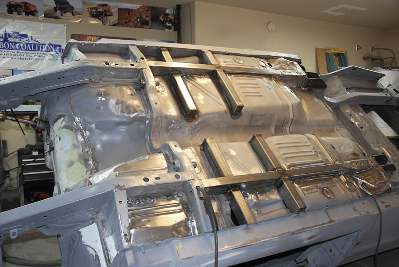
The correct way to do this is with the laser cut sheet metal sub frame connectors that conform to the floor pans and are meant to be fully welded.

Bullsh*t. Ever glue a paper towel wings to paper towel roll and try to fly it? The whole point is to tie the frame rails together using something that resists torsional wringing, 1/8" wall 3x2 does the job fine.

Problem solved!

ROFL!
 
Give the OP a break here: He is trying to help and really believes in himself.
I agree that tying to the floorpan adds in the reduction of sheer and flex to some degree, but unless you have access to a 4 post jig similar to what XV Motorsports used to use, how do you collect accurate data to prove your point?
I have installed 3 sets of frame connectors, all hand built using 3x3x.120 box steel. They were all cut along the top side to match the floor pan then reboxed and welded. In my Charger, I added fabricated torque boxes and welded them in at the same time. The frame connectors were welded at each end and stitch welded to the floor. The car was always pretty rigid but afterwards, it felt better. It soaked up dips and bumps like a new car. Most rattles were gone and the car felt much more solid.
 
Sure helps body sag. I can open and close my door with a corner jacked up now. I think I got about 4 trivial tacks where the rectangle tube hit the floor pan. I didnt want to burn my carpet!
 
wow what a poop storm this started. i modeled mine after the ones on big block darts website. 2x3 box steel .125" thick layed flat. slotted rear foot well. sure they dont attach to the floorpan except in the back footwell, but based on what most folks do it seemed like the way to go. $35 in materials also cant be beat either.

i also made and and installed front and rear torque boxes out of 1/8" steel plate like us car tool does. welded up and reinforced my K frame like firm feel does

still got to build a boxed lower radiator support, and stiffeners for the shock towers to firewall. i would have to agree with 72blunblu about the floor pan. its ridges, and such are there to make it a bit stronger than just flat sheet. will welding the connectors to the floorpan at the forward end where the trans crossmember is help stiffen up the car instead of fishplating them into just the crossmember?? Absolutely they will. But how much stronger is the question, and for how most folks on this forum use their vehicles is doing that extra work just overkill.

dont get me wrong i love the look of the US car tool subframe connectors, but at the time I installed mine I didn't have the money for them, nor did I have a body rotisserie at my disposal. for these two reasons I went with the 2 x 3 boxed steel. for what I intend to use the car for which is autocrossing and to have the handling improved with heavy duty sway bars torsion bars and polyurethane bushings, thats all that's needed.

you can over build to a point and I applaud you for that, but it's just not that necessary for what most of us use these cars for.

remember opinions are like buttholes everybody has one

and here is my .02
Matt
 
wow what a poop storm this started. i modeled mine after the ones on big block darts website. 2x3 box steel .125" thick layed flat. slotted rear foot well. sure they dont attach to the floorpan except in the back footwell, but based on what most folks do it seemed like the way to go. $35 in materials also cant be beat either.

Lol, and I did the same. While I tend to agree with the OP, I cannot dismiss the fact that the way I did mine made one heck of a difference.

I noticed it immediately when I pulled my car out of the garage and onto the street. My driveway is sloped down and when I pulled off the slope onto the flat surface of the street, my response was, wow. Took it for a blast and man what a difference in the way it rides and handles.

I can also jack my car up now and it had zero affect on the doors too.

So, IMO, doing them that way is far better than not doing anything.

NOW, if you have a serious race built car, I would lean toward connecting them through the floor or welding to the floor for torsional stability.
 
Hey thanks for including a pic of my connectors in the "right way" column:D

I have to add though that back in the early '80s I put subframe connectors on my first Dart. By the time I put them on the body had been flexing quite a bit.

I'm pretty sure that the connectors I used were made by Lakewood. They attached front and rear only. I could tell the difference in the way the car drove immediately after installing them. They definitely did help reduce the amount of flex in the unibody even though they were not attached to the floor.


DSC_1425.jpg


What isn't shown is the driveshaft loop which was incorporated into the 2x3 tubing I used for the seat mounts.
 
I used some 2x3 stock for my connectors NOT welded to the floor pan. I can jack the car up evenly by placing the jack one side so I say they seem to be working fine.

Just saying!
 
-
Back
Top