The 360 build that has more turns than Willow Springs

-
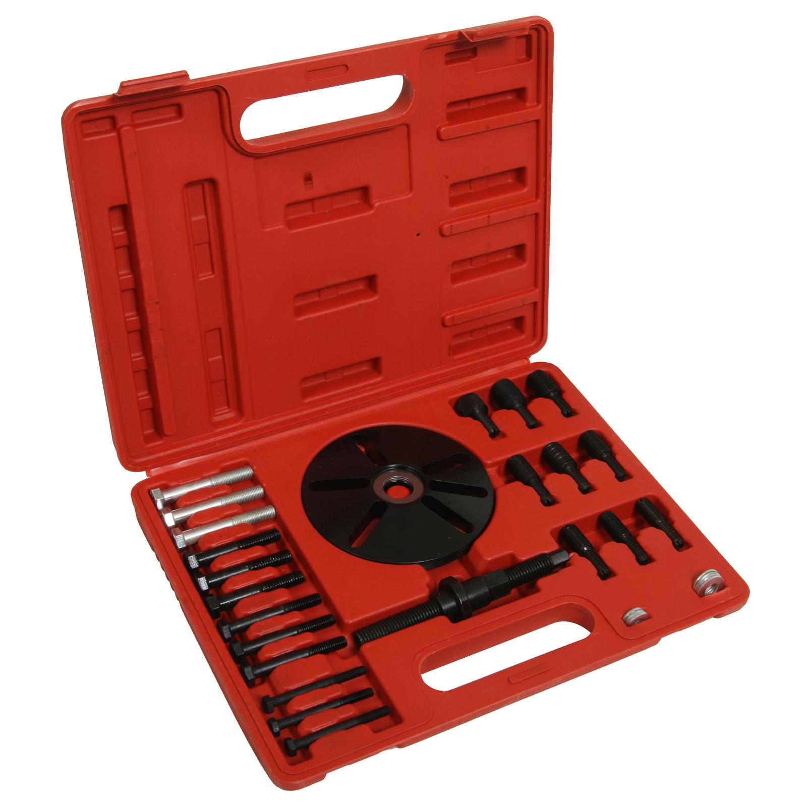
I’m trying to find a low dollar way to install the harmonic balancer. For big blocks, I use this:

View attachment 1716388203

It is a 3/4” bolt with 16 threads per inch. I crank it in until it bottoms out then spin the nut against a washer against the balancer and it sides into place.
The LA And Magnum blocks need a longer bolt. The threads need to be about 1 to 1 1/4” further up the shank. ACE hardware had nothing. I’m going to try a couple construction supply stores next.
I’ll need paint too as I only have half a can left.
When I painted the 440/495 short block, I used about half a pint. I want to spray three engines next… the 360, my friends 5.9/408 and my 5.7 Hemi I bought to replace the original engine in my 2007 Truck…

View attachment 1716388206

Seriously, how much longer can I expect this one to stay together?

View attachment 1716388207

Seriously? Ya cheap phukk. Even my broke azz can afford this. Do it right, dipshit.

 
OR for nine bucks, I can make two of them.
I don't buy what I can make. I have plenty of money, sometimes I like finding creative solutions rather than just buying things. Like many others, I modify tools to fit the needs of certain tasks even if a specialty tool exists.
Go for it. I like tools.
 
Looking good!! I know you probably know, but don't forget about the small core plug under the rear main cap. That's another one that'll ruin your day.

Machine shop forgot oil plug?
000 ZZ.jpg


No, I don't know about that one! What the heck were they thinking with these engines ???
I will look tomorrow. Thank you so much....this sort of thing is like that dang gallery plug....when you don't know about them, they can be overlooked since they aren't immediately obvious.
@RBConvert ....are you getting this too?

***********EDIT***********
Because I would wonder about this and possibly have trouble sleeping, I went out back and saw that my block and Rich's had those plugs tapped into place. Both looked fresh so either our machinist tapped them in OR they are originals that were cleaned when the blocks went through the wash in his shop.
 
Last edited:
View attachment 1716388375

No, I don't know about that one! What the heck were they thinking with these engines ???
I will look tomorrow. Thank you so much....this sort of thing is like that dang gallery plug....when you don't know about them, they can be overlooked since they aren't immediately obvious.
@RBConvert ....are you getting this too?

***********EDIT***********
Because I would wonder about this and possibly have trouble sleeping, I went out back and saw that my block and Rich's had those plugs tapped into place. Both looked fresh so either our machinist tapped them in OR they are originals that were cleaned when the blocks went through the wash in his shop.
It lines up with the oil pressure port where the sending unit or gauge installs. Get a long piece of coat hanger wire and run it down. If it comes out the bottom of the block, the plug isn't there.
 
View attachment 1716388375

No, I don't know about that one! What the heck were they thinking with these engines ???
I will look tomorrow. Thank you so much....this sort of thing is like that dang gallery plug....when you don't know about them, they can be overlooked since they aren't immediately obvious.
@RBConvert ....are you getting this too?

***********EDIT***********
Because I would wonder about this and possibly have trouble sleeping, I went out back and saw that my block and Rich's had those plugs tapped into place. Both looked fresh so either our machinist tapped them in OR they are originals that were cleaned when the blocks went through the wash in his shop.
Go for you for checking. I'm betting it was never removed to begin with. It's an easy one to overlook. It's job is very important though. It's responsible for diverting oil from the pump to the filter. Without it, the pump would circulate unfiltered oil. No bueno for sure.
 
Here is one.....
My 360 has those special ARP main cap bolts with the threaded holes to allow the use of a steel windage tray. I have no intention of installing one but Rich might with his 5.9/408.
I can't imagine that there would be any issue with trading bolts with him so he could install a tray in his engine but maybe I am missing something here?
These oil gallery plugs have shaken my confidence a bit!
I knew of the main seal plug but forgot about it when we were going over our blocks. Don't know if I would've remembered, so thank you everyone.
We didn't take it out during disassembly and it's not something the machinist would have removed and not told us.
 
IMG_0237.jpeg


The intake is clean. Bath time for Edelbrock.

IMG_0238.jpeg


Because I am a bit clueless, I used some Pine Sol and this stuff:

IMG_0239.jpeg


After about 23 hours, it sure is clean.

IMG_0240.jpeg


It is discolored and dark gray….

IMG_0241.jpeg


…but it is clean.

IMG_0242.jpeg


IMG_0243.jpeg


I had thoughts of painting it engine color, then I thought of using dull silver header paint.

IMG_0244.jpeg


Like this:

IMG_0245.jpeg


To me, nothing looks as nice as a natural finish on aluminum parts like heads and the intake but when you drive a car with exposed and unpainted parts, they don’t stay clean. The aluminum is porous and any smudge or oil drip sticks and stays. This header paint will provide some measure of cover over the aluminum to make cleanup easier. I do plan to spray some clear over it.
 
The color isn't an exact match to bare, cast aluminum....

IMG_0256.JPG


IMG_0257.JPG


IMG_0258.JPG


It looks better than when this all started...


1744089346931.jpeg


This crankshaft was in great shape and all the bearings were fine but I replaced them anyway. I laid the crank but stupidly left the rear main seal out.
When I get to talking, I sometimes miss things! The same thing happens when I'm driving....If I'm talking too much, I miss my exit!
I looked through the stash and found numerous 273-318-340 spec rear main seals but none for the 360. I have numerous oil pan seals, pan gaskets, other leftovers from various builds or stashes of parts I've taken in from friends. How odd it was to not find even ONE 360 oil seal. I went to a NAPA store. $32 bucks for a dang oil seal? An entire gasket set from Summit is not much over $100!
Grainger had the 3/4" x 16 TPI all-thread I ordered on Friday. I can make two tools to install harmonic balancers with the 12" section I got. $9.52!
 
I’m Encountering some stumbling blocks that may be old hat to a lot of you. One is piston orientation. With most stock pistons, it is easy… no valve reliefs and they usually had a notch that went toward the front. With aftermarket pistons, usually the valve reliefs are obvious because the big one is for the intake, the smaller is for the exhaust.


IMG_0276.jpeg


These are the KB 107s.

IMG_0275.jpeg


Looking at these, I can’t see a difference in the size.

IMG_0277.jpeg


I measured from the edges of the reliefs to the edges of the piston but given my cheap calipers and the likelihood of being out of square, I got inconsistent numbers.
I did a search on this site to see if anyone else made note of which way these pistons go in. Maybe my manner of phrasing the question wasn’t good enough but I found no clear determination. At one angle, one side looks a little bit larger but if I blinked and moved the piston, they looked the same size.
A call to Summit racing….
The man would not clearly say “Oh yeah, they are symmetrical “. He did state that the depth of each notch was .028 deep and that they were the same width. Maybe lawyers prevent him from making outright claims?
Reading between the lines, it seems that these are symmetrical.
 
Engine paint day.

IMG_0292.jpeg


Since this engine is not meant to resemble a stock restoration, I went with a tangy orange color sprayed through a cheapie Harbor Freight paint gun.

IMG_0293.jpeg


I forgot to tell them to leave out the metallic but looking close, I can’t see any. I painted the 360 and a 340 I have stored for years.

IMG_0280.jpeg


I looks like you could lick it.

IMG_0281.jpeg


I painted the heads and balancer separate. The head bolts and oil pan bolts will be cleaned but stay natural color.

IMG_0288.jpeg


The intake, timing cover and water pump will be painted dull aluminum.

IMG_0289.jpeg


IMG_0290.jpeg
 
There were a few fish eyes in the 360 block and oil pan. The primer went on fine but the paint didn't.
I painted the heads, they looked okay. The 340 I painted looked fine too. I am not 100% sure what caused the fish eyes but I think it might be contamination in the air line. I forgot to route the line through my water trap. Today I bled some air from the compressor and there is a fair amount of water in the tank. I'm going to drain it and let it refill before the next application of paint. I think that since the first few shots of paint I sprayed were on the 360, the initial spray was contaminated with water from the line. When I sprayed the parts that came out okay, the water must have already passed through the line.
I'm just guessing but it makes some sense. The primer is from a spray can and it sprayed and looked great on everything.
I tried to sand the flaws out of the oil pan but ended up having to strip it all the way down to bare metal to start over. I don't mind a few flaws here but some looked so obvious, I'd look like a real hack to just let them remain.
Post #136 above posed a question about the pistons and the valve reliefs in them. I was trying to determine which cylinders each piston will go in and while looking at the valve reliefs, it wasn't obvious which side was intake, which was exhaust. In other heads, it is often immediately evident...

DSCN1913.JPG


The Ross pistons (From my previous 440/493 build from years ago) above are one example.
With these KB 107s, I couldn't tell.

KB VR1.jpeg


Some old school pistons have valve reliefs top and bottom like so:

446 B.JPG


With some pistons, the valve reliefs look identical, making the pistons symmetrical and able to work in every cylinder as long as the notches are above centerline and aiming toward the intake.
With these KBs, I'd measure them but get inconsistent numbers since I was trying to measure them with cheap calipers on curved areas with no guarantee that I was measuring squarely. THEN....FABO member @413 suggested that I try using something round as a gauge to hold against the curved edge. GREAT idea, it was right along the lines of my usual thinking but this time it didn't occur to me.
Here is a 2.19" intake valve for a big block Edelbrock head:

KB VR2.jpeg


Same radius, same curve. Now, the right side:

KB VR3.jpeg


Forgive the imperfect pictures...It might look like there was more of a gap in the left pocket but they are the same. I have 1.88" intake valves here so as far as I can tell, these pockets are the same and my valves would easily clear both sides.
 
Last edited:
There were a few fish eyes in the 360 block and oil pan. The primer went on fine but the paint didn't.
I painted the heads, they looked okay. The 340 I painted looked fine too. I am no 100% sure what caused the fish eyes but I think it might be contamination in the air line. I forgot to route the line through my water trap. Today I bled some air from the compressor and there is a fair amount of water in the tank. I'm going to drain it and let it refill before the next application of paint. I think that since the first few shots of paint I sprayed were on the 360, the initial spray was contaminated with water from the line. When I sprayed the parts that came out okay, the water must have already passed through the line.
I'm just guessing but it makes some sense.
I tried to sand the flaws out of the oil pan but ended up having to strip it all the way down to bare metal to start over. I don't mind a few flaws here but some looked so obvious, I'd look like a real hack to just let them remain.
Prepping a block for paint, masking, and then shooting the paint is a long, tedious process. Greg and I spent most of yesterday prepping our blocks and bolt on's. Then again today for a few hours. Man, I don't know how those UT guys do it in under an hour.
 
It looks like the Fish Eye problem is gone for now. I did reroute the air line to the water trap after draining the air compressor tank completely.
 
Look on the KB pistons on the side of the piston where the pin comes through. The part number will be there and I believe there is an "F" for front on one side to give you piston orientation.
 
It looks like the Fish Eye problem is gone for now. I did reroute the air line to the water trap after draining the air compressor tank completely.


The first to get paint today was my oil pan. There are other parts on the table that are for Rich’s engine.

IMG_0333.jpeg


The metallic is very subtle and if you didn’t know to expect it, you may not notice.

IMG_0335.jpeg


It looks like an engine factory in small scale…

IMG_0322.jpeg


The 1990 360 of mine:

IMG_0323.jpeg


IMG_0328.jpeg


Here you’ll see the Fish Eyes:

IMG_0329.jpeg


IMG_0330.jpeg


1970 340:

IMG_0324.jpeg


Core plugs will go in then I’ll just stow it until I’m ready to assemble and sell it.

IMG_0327.jpeg
 
Rich’s 2001 crate 360 that is featured elsewhere on this forum.

IMG_0325.jpeg


On the initial primer coat, I saw areas where Fish Eyes were starting so I went over the block with Acetone.

IMG_0326.jpeg


Rich took it from there. This was his first time painting an engine with a spray gun. He did a great job.


IMG_0331.jpeg


No Fish Eyes. This turned out nice for him.

IMG_0332.jpeg


He is going a different direction with his build. Same Air Gap intake but….

IMG_0334.jpeg


He spent the money on heads!

IMG_0336.jpeg


IMG_0337.jpeg


That rough edge at the bottom part of the heads is making tape used to cover the deck surfaces. This should all clean up nice.

Look on the KB pistons on the side of the piston where the pin comes through. The part number will be there and I believe there is an "F" for front on one side to give you piston orientation.

Good idea. Here is what every piston has on the sides:

IMG_0338.jpeg


KB 107, okay…

IMG_0339.jpeg


SL for Silvolite? 24 ??
 
Last edited:
It is not an F although at first glance, I thought you saw something that I didn’t.

IMG_0341.jpeg


Closer…

IMG_0340.jpeg


That mark is on all four spots of the piston at the lower corners.

IMG_0343.jpeg


That could have been a good catch if it were a real F mark.

IMG_0342.jpeg
 
The Woodruff key to locate the cam sprocket and fuel pump eccentric fell out of the groove in the cam when I was disassembling my engine. I did take this picture of Rich's engine to remind me of how it looks when it is installed right:

360 A69.JPG


360 A70.JPG


While I'm no newbie, I admit that it has been awhile since I built an LA series engine so some of their parts and procedures are different than big blocks.
I did put in the rear rear main seal and lay the crank. The bearings all came in at .002 clearance except the thrust bearing, that was at .00175. I measured thrust clearance, something that I have never done before. I came up with a .004 number, right within the range.
I need to file fit the rings, chase the threads in the block and clean all the bolts for the rest of the assembly.
 
-
Back
Top