Why are the easy answers the hardest? Using the OEM fuse box and stock harness for a G3 swap

-

DionR

Well-Known Member
Joined
May 7, 2008
Messages
6,752
Reaction score
3,923
Location
Spokane, WA
So why not use the ’06-07 front fuse box and FCM or the ’08-10 TIPM when doing a G3 swap if the NGC controller is used? Because I think you can. Well sometimes, depending…let me explain.

But first a little background.

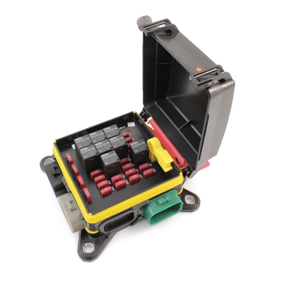
I decided awhile ago that I didn’t want to try and hide the PCM inside the car. It looks better for sure, but I decided to just keep it in the engine bay like the OEM application. One nice advantage to this is I can use a car engine harness virtually as is, provided you aren’t using an ’08 harness on an Eagle 5.7 or 6.4 (yep, that’s what I will be doing) and the harness isn’t cut or connectors smashed when it was removed. The harness is pretty much self-contained and appears to be able to be installed before the motor is dropped in, which is nice. There are only 2 plugs that reach beyond the motor and they are the orange C2 plug on the PCM and the C100 plug that is usually under the cowl support bar.

1754526279507.png


1754526302451.png


The problem is that it doesn’t include the C1 or C3 plugs for the PCM. And the C100 plug is where power for the coils and injectors is connected plus controls for the #7 and #8 injectors and coils. So, the C100 plug generally gets cut off and the two missing plugs grafted in. But what if someone just stripped out the un-needed wires from the section of the original harness that had those plugs? While I don’t like plugs where one isn’t needed, it would mean no splicing of wires (sometimes worse than a plug) and it would mostly be easily done minus trimming wires out.
 
So I went to a JY and cut the passenger side engine compartment harness off at the firewall and took it all home. Didn’t care about the harness beyond the PCM plugs, but didn’t see the need to stand there and cut stuff off since it was all loose anyways and it didn’t cost me extra.

1754526435046.png


1754526456969.png


Then I got to looking at it and thought, what if I used the front fuse box as well? It is missing the fuel pump relay (it’s in the trunk PDC), but the rest of it is pre-wired and I have a couple of TIPM’s I have collected over the years. And maybe I could leverage some of the other options, like running the stock radiator fans rather than having to buy an aftermarket fan controller. So, down the rabbit hole I go…
 
First thing I looked at was if I was ok with an even bigger box in the engine bay. I had planned to buy one of these and they measure about 6x6 while the TIPM I have is more like 6x12 if I include the large battery connection.

6ac2ea24cfcd13d_lg.jpg


Not sure how I feel about that yet, but the economy of it plus being mostly pre-wired and additional options makes me think maybe I can get over it. We will see on that part, still up in the air.

So why do this besides saving money on a $200+ PDC? And don’t forget, that doesn’t include the connectors, terminals, seals or retainer that add something like $50. Couldn’t I do it with a much cheaper PDC? Places like Hotwire certainly do.

My list of things the above PDC would have housed included two ASD relays (the stock system has 2 circuits off the one relay), fuel pump relay, starter relay, A/C relay (for someday) and high/low headlight relays. That’s 7 relays and fuses, plus another fuse for the PCM. The fuel pump relay could probably move to the trunk either way, so a minimum of 6 relays and fuses in my case. Really didn’t find much that was as compact as the one above and bussed so I didn’t have to wire power and relay control to each relay. And I see no reason to add a 3 relay PDC to run the motor and other relays randomly placed about the engine compartment, rather have them all contained in one box.

But the above PDC has a weakness or two. The max amps for each output terminal is only 30A. That was why I planned for two ASD relays as the 2 circuits off the stock ASD relay both use a 25A fuse which made me feel like I was pushing my luck running on a max 30A output. Plus, the PDC uses 4 pin micro relays only. So, it felt like the PDC was a little limited and wouldn’t work at all for something like radiator fan controls, even if there was room for the relays.
 
The stock fuse box or TIPM is already pre-wired and sized for the following:

ASD relay
Run/start relay (TIPM only)
Starter
Radiator Fans
Headlights
A/C relay
ABS

But, could I make all those work? Because if all I really get is an ASD and starter relay out of it, there isn’t much point. That’s where the answer is maybe, sometimes, depends….

ASD

This is a slam dunk. In both the earlier box and the TIPM, the only control is the PCM. So, no work there beyond wiring it up.

’06-07:

1754526662392.png


TIPM:

1754526678629.png


Run/Start

For the ’06-07 setup, the run/start relay doesn’t exist. There is a key-on wire direct from the ignition switch that would need to be connected, and the only trick is the PCM C1/12 pin would need to be spliced into the same wire as that one was originally powered from the Front Control Module (FCM). If someone were to want to keep the FCM, it might be worth working out what inputs it needs to see to power that wire, but I didn’t go looking to see. And even then, the easy answer is to splice C1/11 and C1/12 together.

For the ’08-10 TIPM, it is much harder. Best I can tell, the TIPM sees a message on the CAN C network from the WIN (i.e. ignition switch) and then it closes the run/start relay. I’ve played with changing the configuration on the TIPM so it doesn’t look for the WIN on the network, but to no avail. There is a key-on wire from the WIN that goes to the TIPM which (in theory) should work and could be replaced with a key-on wire from an A-Body switch, but the TIPM doesn’t seem to care and only wants the signal on the network. So, this will need to have the message sniffed and a box built to inject it into the network, or ignore the relay in the TIPM and power the PCM C1/11 pin direct from the switch.

Starter

This one is also easy for the ’06-07 box. The starter relay in those is completely separate from the FCM and works fine without it attached. No hoops to jump through.

1754526741050.png


For the TIPM, it isn’t easy at all. The wiring diagrams show a run/start input from the WIN and a brake light input, but so far it won’t work. Best guess is there is a message on the CAN C network and it will need to be duplicated to use the starter relay in the TIPM.

1754526760418.png


Radiator Fans

The biggest plus in my mind is the radiator fan controls. After looking at wiring diagrams until my head hurts, I am pretty sure that if the CANBus wires are hooked up, I think it would work. The only caveat is that the ’06-07 fuse box will need the FCM plugged in as well. The ’08-10 TIPM has the circuit board integrated in so there is no option to run the relays without it. This is huge to me, all the big relays, correctly sized fuses, heavy wires, factory logic, everything is there already. And no hacking, just make sure there is communication between the TIPM or FCM and it should work.

Headlights

For the ’06-07 fuse box, the headlights appear to pretty much run direct from the FCM. There are no relays in the box that power them beyond an HID relay. There are fog and marker light relays, but the control side is wired to the FCM. But there are a couple of relays that seem to be completely exposed, meaning power in and out and both control pins are connected to plugs in the wiring harness. Because they don’t rely on the FCM to ground or power the control side of the relay, they could be co-opted to work as headlight relays. These would be the HID relay and the transmission relay. Assuming both are always pre-wired.

1754526790307.png


1754526798222.png


Unfortunately, there isn’t anything available like that for the TIPM. It will require sniffing the CANBus network for the appropriate messages and building something to put those same messages on the network.

A/C

This will almost certainly require hacking the CANBus to send messages to turn that on. The earlier box wires the A/C relay to the PCM for controls, but I suspect the FCM is involved to tell the PCM to engage the clutch. The TIPM is probably even further integrated. For now, that will have to be a someday project.

ABS

I doubt anyone will care about that but me, so I am going to ignore it other than to say the wiring is there and other than a key-on connection there isn’t anything to do.
 
Last edited:
TL/DR?

Let me try and sum it up.

’06-07 Fuse box and FCM:

Best I can tell, the ASD, starter and headlights could be done with this box even if the FCM isn’t plugged in. With the FCM included, radiator fan controls should work. The fuse box might even be slightly narrower than the TIPM, but with the FCM attached it is a fair amount taller.

Without the FCM attached, I could even see this box working to run an ’08-10 NGC controller. But I am not sure if the FCM and PCM would communicate if someone wanted to try and use the radiator fan functionality.

And this one allows for headlights using build in relays without any network gymnastics.

I should add that it seems to me that I heard somewhere the FCM should be avoided as it is frequently an issue. But I can’t confirm that, just seems like I have heard that.

’08-10 TIPM:

Only the ASD and radiator fans function easily. The run/start relay could be ignored and key on power wired direct to the PCM, but the starter relay either required a separate relay or a WIN emulator.

Funny thing about the idea of a WIN emulator is one of the reasons I didn’t try and run a GPEC2 PCM is because of the issue with starter controls. Now I am looking at building something similar. Ugh.

Due to the issue with using the TIPM to power the headlights, it feels like sniffing the network for messages is almost required. In which case, might as well include the starter and run/start messages function. I wouldn’t be surprised to find out that there isn’t even a starter signal wire in the C1/30 pin position in the harness I have.
 
Do either of those setups use a push button starter? That might explain the brake light wiring on the one and the WIN setup. Start signals would more than likely be CAN based for a push button setup since they prevent you from re-engaging the starter once the engine is running if you push the button again. Guessing those would probably be coming from a BCM, though maybe that's the WIN module. I'm not as familiar with all the various modules in the cars today off the top of my head.
 
It can be used, but it is a little overkill for what I would actually need. (Only need 4 relays and a handful of fuses)

I bought a 2015 5.7/8HP trans drop out with wiring harness, just to play around with and see if I could make the factory harness work. I sorted and removed the un-needed wires from the harness & TIPM (Totally Integrated Power Module), I had to add a relay for the fuel pump (actually just wired one of the extra relays in the TIPM for this)

So now, I just to attach 12v from battery to the stud on the side of the TIPM, and to the Starter power cable on the engine harness. Then I am ready to go.

Just for the record, I couldn't start the engine until I sent my PCM out to get flash by Sublime. After that, it fires right up.

Unfortunately that's where I stopped, it appears I need a CAN bus signal to apply the brake signal to shift out of park.

Here is my test stand and wiring diagram:

Engine run stand.jpg


Front PDC with wiring.jpg
 
Do either of those setups use a push button starter? That might explain the brake light wiring on the one and the WIN setup. Start signals would more than likely be CAN based for a push button setup since they prevent you from re-engaging the starter once the engine is running if you push the button again. Guessing those would probably be coming from a BCM, though maybe that's the WIN module. I'm not as familiar with all the various modules in the cars today off the top of my head.

The WIN was used on all '08-10 cars. Here is what it looks like:

2010-dodge-charger-win-module-68210150ab-programmed-w-keys-13.png


Not sure what the '11+ models used, but I know the '06-07 use a more conventional switch with power in and out only. The WIN is connected to the CANBus and also controls things like remote starts and such while the '06-07 switch does not connect to the network.

Interestingly, the push to start feature on this generation of cars is really just a button plugged into the same hole as the key, and it can be removed.

71D+ezbd5iL._SX466_.jpg


The push button option does require the brake pedal to be pressed to start the car, but the regular key does not. Not really sure why. Either way, the brake input isn't from the WIN, it's actually an input to it and to the TIPM. Both are getting a power input from the brake light circuit. I didn't look up the '06-07 setup, but my guess is that there is a brake signal input to the PCM. Either way, the PCM controls the starter motor by grounding the control side, but in the '08-10 TIPM the starter relay control is powered by the TIPM and the TIPM has to want to supply that power.

There really is a fair amount of overlap between the functions of a BCM and the TIPM, both store and apply features and options for the configuration. I guess the only real difference is the BCM is a circuit board inside the car with a front and rear PDC while the TIPM is both the front PDC and BCM. But there isn't a separate module in the car that functions like a BCM does in the '11+ cars. Best guess is that the separate BCM was introduced at the same time they went to the GPEC2 PCM.

It would probably be more accurate to call both the '06-07 and '08-10 setups a TIPM. I've been using the label FCM for the earlier ones, but really that is a part of the fuse and relay box and together they make a TIPM. So the big difference between the two styles is the circuit board on the earlier ones isn't integrated and could be removed.
 
Ah, okay. I'm familiar with that key style as my parents' Ram had one. Interesting that the push button was set up like that. Would make sense for the WIN to control the remote start stuff as well, and it has the same kind of functionality to prevent starter engagement if the engine is already running (though I guess now that I think about it, the PCM is really probably the one that would carry that logic). Pretty wild how limited in scope some of those modules would be. The WIN feels a little silly because ultimately you're not saving much by using it. You'd still need a minimum of 4 wires (power, ground, CAN Hi, CAN Low). If it was just a dumb switch like old cars you'd have the same number of wires or less (accessory, run, crank, etc.) and could just feed those into something like a BCM that carries the logic already. Guessing it must have been an "add-on" so they could use other existing modules and add functionality without having to alter code. Or maybe they just ran out of I/O on what they had at the time, so throwing it on CAN was an easy way to extend it until they could requote a new controller with more I/O or something like that.
 
It can be used, but it is a little overkill for what I would actually need. (Only need 4 relays and a handful of fuses)

Completely agree. For me, the biggest plus is fan controls. The GPEC2 can control the dual fans directly without using the TIPM, but the NGC uses CANBus messages to the TIPM so it is this or an aftermarket controller.

I bought a 2015 5.7/8HP trans drop out with wiring harness, just to play around with and see if I could make the factory harness work. I sorted and removed the un-needed wires from the harness & TIPM (Totally Integrated Power Module), I had to add a relay for the fuel pump (actually just wired one of the extra relays in the TIPM for this)

So now, I just to attach 12v from battery to the stud on the side of the TIPM, and to the Starter power cable on the engine harness. Then I am ready to go.

Very cool!

I wish my TIPM had spare relays that were open to being co-opted, but I don't see one.

Just for the record, I couldn't start the engine until I sent my PCM out to get flash by Sublime. After that, it fires right up.

Yep, that's the due to the factory tune requiring a start message on the network. There is (was?) a replicator (SSR) someone was building but they were ridiculously expensive and Blake commented in a video that they flood the network and cause problems or fail entirely. It's a major reason why I pivoted away from the GPEC2 controller as I didn't want to have to have a crate motor flash.

Note that when I was looking at it, it was before several places were offering to flash PCM's and I didn't want to be tied into a PCM I couldn't replace. Now they are much more prevalent, so much less of an issue now.

Even worse, now I am looking at building my own SSR. :BangHead:

Unfortunately that's where I stopped, it appears I need a CAN bus signal to apply the brake signal to shift out of park.

I wonder what Sound German Engineering does for that. They must have a work around, I know they want a brake light input but not sure how they use it.
 
The WIN feels a little silly because ultimately you're not saving much by using it. You'd still need a minimum of 4 wires (power, ground, CAN Hi, CAN Low). If it was just a dumb switch like old cars you'd have the same number of wires or less (accessory, run, crank, etc.) and could just feed those into something like a BCM that carries the logic already.

I think the big thing is that the WIN is the security gateway much like the tumblers in an old school switch.

1754600580460.png


So the WIN has to have some kind of RFID or similar mechanism.

And this also includes some kind of a handshake with the PCM which includes the VIN and a secret code.

Add that there is also a solenoid that locks the key out of the off position and keeps it from being removeable if the rig isn't in park. So, much like the function where the shifter can't be moved out of park until the key is turned, the key can't be removed until the car is in park.

After looking at this a little more, the '06-07 have something similar.

1754601145561.png


So even though a key can be inserted to turn the switch and power things and the switch itself is much simpler, there is in addition a ring that reads the key and determines if the key is valid and if the car should start. So it's not like the WIN is doing a great deal more than the earlier setup, more that it is all combined into one module.

1754600053994.png
 
It's not my favorite look, but I think I can live with it. The bundle across the shock tower should be much smaller after I thin it out, and I might try and go through the back of the inner fender and hide it. Time will tell.

20250806_183604.jpg


20250806_183619.jpg


20250806_183629.jpg


No worse than having the battery on the other side.
 
I think the big thing is that the WIN is the security gateway much like the tumblers in an old school switch.

View attachment 1716439284

So the WIN has to have some kind of RFID or similar mechanism.

And this also includes some kind of a handshake with the PCM which includes the VIN and a secret code.

Add that there is also a solenoid that locks the key out of the off position and keeps it from being removeable if the rig isn't in park. So, much like the function where the shifter can't be moved out of park until the key is turned, the key can't be removed until the car is in park.

After looking at this a little more, the '06-07 have something similar.

View attachment 1716439286

So even though a key can be inserted to turn the switch and power things and the switch itself is much simpler, there is in addition a ring that reads the key and determines if the key is valid and if the car should start. So it's not like the WIN is doing a great deal more than the earlier setup, more that it is all combined into one module.

View attachment 1716439283

Ah, that would make a fair deal of sense. Didn't think about the communication between the key itself and the unit.
 
I am absolutely jacked!! I'd about given up hope but all of the sudden I have the starter relay engaging!

As I said above, the ASD relay was easy. The run/start relay required adding in the WIN module but with that I got it sending power. But everything so far has been a dud for getting the starter relay to work. I have been able to get all three modules (PCM, TIPM, WIN) programmed with the same VIN, and even got a key programmed (I think). But nothing from the starter relay.

I did start to have the problem where the key couldn't be removed from the WIN module after I programmed it too. Turns out the "TRS Park Sig" circuit needed a ground to tell the WIN the car was in park.

I also figured out that the PCM I am using to test is from a car with a 2.7 and a 42RLE. It appears that the 42RLE doesn't have a "smart" shifter, so no CANBus connections. So I started poking around on the C4 pinouts and found a similar "TRS Park Sig" circuit there, so I added a ground to that pin and just like that, the starter relay puts out power. I guess the PCM is the source for the "in park" message, I assumed it was the WIN.

What a relief. Now I just need to get more sophisticated with my CANBus sniffing so I can figure out what the required messages are.

Sweet!!!
 
Whoo hoo!!!! Stoked!

I got the run/start relay to close with the message I sniffed! Even better, I got the starter relay to close with a different message!

I think I have the messages I need to feel like I can make this work. Lots of work left, need to figure out some things like what the WIN replicator will look like and what to use to build it. And more testing. Over the moon to reach this point.
 
Still playing with this, started trying to work out how to use this box to power the headlights. Don't have the messages yet because I can't get my sniffer to connect to the CAN-B network for some reason.

Nice thing about using the TIPM is, power is direct from the battery/alternator to the headlights. Plus it is one headlight per wire rather than both headlights on one wire.

Bad thing is (was) my TIPM came out of a quad headlight Chrysler 300 which meant when the high beams were on, the low beams were still powered. But since these boxes are logic driven, just had to disable the quad headlights and now it works like I need. Pretty cool.

There is also the option to run some fog lights out of the same box. Add a button in the cab and an input wire to the box I will need to build and I could have them powered without having to run wires thought the firewall. Not in the plans, but an idea to keep in the back of my mind.

I thought about running the parking and turn signal lights off the TIPM as well, but that looks way more complicated than I want to deal with. So I think I will leave that stuff alone.

Now if I could just figure out why my sniffer won't sniff the CAN-B network.
 
This kind of reminds me of the Isis CAN based power control modules (or at least I think that's what they were called). Basically "smart" fuse boxes. It's kind of temping to build one of my own the more I read about you playing with the factory one, but I'm not sure it would really gain me that much at the moment. I'm using the factory bulkhead connector for all of my chassis control stuff now and still have a couple of cavities open if I recall, so wouldn't really save me much other than trimming down some bulk on the harness right at the firewall.

I've often wondered about "universal" body control modules. They have universal PCMs now (like the Holley stuff, Megasquirt, etc.), but to date I've never heard of a generic body control module. Probably because they tend to be a lot more complex and tied into other stuff/proprietary, but it's always been in the back of my head what I would do if the one in my Viper craps out one of these years. In many regards it's a pretty simple device. It's basically just a fancy power control module that takes inputs and controls outputs, though I know that's really oversimplifying it.
 
I remember when ISIS was the hot thing. I was completely enthralled with the idea, even started making plans to build my own using a Raspberry Pi because the ISIS stuff was so expensive. The idea of controlling all the rear end lighting with a couple of bus wires instead of a bundle of wires, and being able to do things like flash the tail lights a couple of times when you hit the brakes just sounded cool.

Looks like ISIS is gone, probably after the terrorist group of the same name hit the scene. But it looks like they were sold and rebranded as InfinityBox. I also found this - ST - BCM.

Funny thing is, I didn't even think about the multiplexing stuff in this case. Kind of came around by accident. I just know that I will need relays and fuses and just kind of tripped over the idea of using the OEM box. And I knew that this would give me fan controls so that solved that issue and made it easy since I plan to run an OEM radiator and fans. But since I planned to run relays for the headlights in the PDC I was going to buy, if I am going to avoid an additional relay box, I need to figure out how to make the headlights work out of this one, too. And just like that, I am multiplexing. :D

Not sure yet how much this will save me in wiring. If I get the headlights to work, that's 2 wires I can remove, but if I have to use the CAN-B network to pass the messages, I will have a total of 4 CAN bus wires to pass through the firewall somehow for a net gain of 2. In theory, I might be able to save some wires I would need otherwise, like an AC command wire, but I am also going to probably have to pass 3 wires through for the CC since the truck PCM I plan to run uses direct wire inputs. And I will still need a key on wire, either the starter relay control is powered through that input or the TIPM wants to see it. But I won't need the yellow starter wire anymore. So a net gain of 4 wires through the bulkhead connector if I don't pass them through a new hole? And I know of a couple of power wires direct from the battery I will need to figure out as well.

I'm pretty excited to start stripping down the harness I have. But I don't want to get ahead of myself and strip wires out that I might want later one.
 
Yeah, I never would have realized the fuse box was CAN based at first glance. I know they are pretty complicated nowadays, but I would have guessed it was more of a "dumb" box and the BCM did all the work. It would make sense that that isn't the case though, for the very reasons you're talking about with wiring.
 
I would have actually been ok if it had been more of a dumb box, I really just wanted to use the prewired fuses and relays and having to work out the CAN stuff wasn't part of the plan. The '06-07 box is simpler in that the run/start and starter relays don't use CAN message inputs, but I suspect stuff like lights would still need it. But the earlier box is bigger, the actual logic module is on the side instead of inside the box and (I think) they are more delicate so I prefer the '08-10 box if I can get it to work.

Technically, the TIPM is the BCM. They went to a separate BCM in 2011, but for the '08-10 cars this is it.

For a simpler swap, I think the '06-10 setup is going to be pretty nice. The wiring and fuses are all pretty easy to integrate into the old car and if my WIN replicator (or whatever it is) works well, it shouldn't be difficult to make work. I like the GPEC2 controller, but with the BCM being under the dash, I suspect the wiring would be harder to use as is even if the relay box under the hood is simpler since (in theory) it doesn't have a circuit board in it.

Not that everyone is going to like the look, but in the end it might be a couple wires to hook it up much like an aftermarket harness but at 1/4 the cost. And the aftermarket harnesses for a NGC4 controller don't take care of radiator fan controls and don't have the (potential) option to run headlights and such.
 
It can't look too much worse than my giant 40 fuse/10 relay box that has to sit on stilts because it all wires in from the bottom and I didn't want to cut up my fender to do that, lol.

I agree, a circuit board with all the fuses and relays built into it with cleaner power distribution is a very nice way to go. Every relay I add to my box I have to add either a dedicated ground or power wire to, and the easiest way to get power is to hop over to one of the fuses, so nearly every one of my relays has two fuses on them, one for the coil and one for the power load itself. Tons of little jumper wires under the box that are annoying, but the functionality is nice.
 
What a roller coaster. Turns out these TIPM's use a low speed type of interior CAN network that isn't really used anymore and isn't easy to tap into.

So the '06-10 Charger/300 and '08-14 Challengers use an 83.3kbps CAN-IHS (Can-B) network that is what is called a Fault Tolerance system. This FT system uses a completely different method of sending messages and (no surprise) doesn't work with the available CAN shields that I can find. They take a completely different transceiver chip and no one seems to offer a card that uses it.
1757355060849.png

The later cars use a 125kbps slow speed network that still uses the same architecture as the high speed bus and isn't the FT style. Those can be connected to using the available CAN cards like I have.

I did find one guy (BiggRanger) that documented how he was able to get connected to and send messages to a radio that used this style CAN network. Thankfully he has a bunch of documentation on the messages, so I might have the messages I need to send to turn on headlights and such. He effectively put the bus into fault mode by leaving the CAN-L wire disconnected on the radio he was working on and hooking the CAN-L wire on his card to ground through a 120ohm resistor. Pretty sure that put two 120ohm resistors in the circuit. And then he hooked the radio ground to the card as well.

I haven't tested thing yet to see if I can even make it work. And the current hookup kind of feels wrong to use since it puts the network in a fault state. But to do it other wise might require a custom circuit board with the correct transceiver chip.

Oh, and as an additional wrinkle, the TIPM turns on the headlights automatically when the CAN-IHS bus is down. This might be designed in as a fault mode, or it might be that the headlights are defaulted on and the IP sends a "headlights off" message and if the TIPM doesn't see the message it leaves them on. So if I can't get the TIPM to turn off the headlights I might have to actually fool the TIPM into thinking the IP is connected. That could be a ton of work.

I just got my 120 ohm resistors to try connecting to the TIPM using BiggRanger's method. And I still have to modify his code to send headlight messages instead of radio messages. So time will tell.
 
Wow, that is pretty odd. I guess the headlights would probably be considered a critical safety system though, so I could kind of understand them being on a more specialized network. Strange that it's such a "proprietary" one though. You'd think they would have dug into their usual bag of tricks and grabbed something like the KP2000 or other SCI/PCI based busses that had been used for years as opposed to something so unique. I guess maybe they had the same lack of fault tolerance though.

That being said, it's not like the car won't work without headlights if they were burnt out, so it's a tiny bit weird they seem to be on the "backup" network. I'd kind of expect them to exist on both, as it they could respond to a "headlights on" message on either bus. That seems like a more fault tolerant design in the long run, but OEMs will be OEMs, and controller systems always have some interesting wrinkles.
 
I'm not sure it is a proprietary architecture. The bus is sometimes referenced to as ISO 11898-3 compliant, and if anything is just older. But not really sure. I am pretty sure it is speed limited and is close to topped out while the more current stuff has a much higher speed but can be slowed down to 125kbps easily.

I've seen discussions that the CAN-B/CAN-IHS is used for comfort stuff, like heat/AC, while the CAN-C is used for critical stuff like PCM stuff. I could see the argument that headlights are critical, but seems they left that on the IHS bus.

I did tried and send the messages for the headlights on the CAN-C bus just to see if it would work but didn't seem to have any changes. But I don't have confirmation that the messages are even right yet. The ID's I have are for a 2008 Durango, so there is a good chance I will still have to try and figure out how to sniff the correct ones.


-
Back
Top Bottom