You are using an out of date browser. It may not display this or other websites correctly.
You should upgrade or use an alternative browser.
You should upgrade or use an alternative browser.
Faulty battery, bad alternator, or both (photos)
- Thread starter Saverio
- Start date
-
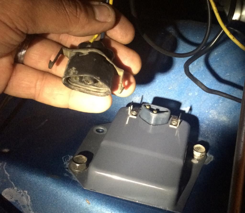
Find a garbage can for that electric choke assist. It may have been your initial problem.
You don't need it. The choke works just fine without it.
Ah! so I should be ok bypassing it altogether?
That makes things a lot easier (and cleaner for wire routing), if so!
Thanks RedFish for the input!
NO. "bypass" as in run 12 volts directly to the choke assist is not the plan. Don't bypass the controller. Disconnect the wires and leave them off. The original thermal activated choke is still in the well. The electric assist can stay in there too, just don't supply power to it.
Do this... After you remove that old school controller, bend its tangs back and open it. You'll see.
Do this... After you remove that old school controller, bend its tangs back and open it. You'll see.
Well I'm back at it.
After looking at wires and such, I thought I better inspect the engine bay/ fender mounted ballast resistor since this part always seems to be a "gotcha".
I noticed I had wires that weren't checking out in terms of continuity from the bulkhead connector to the steering column connecter for the ignition.
PRIOR to changing out the ballast, I was NOT getting continuity in the (L to R) Black, Brown, Orange, and Blue (2nd from right) wires.
AFTER swapping the ballast, the only wires that don't show continuity are the Brown and Blue (2nd from right).
Hmmm....
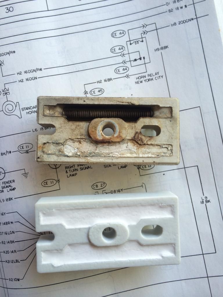
Here is what the old one looks like compared to the new one I bought:
Front:

Back:
AND I decided to check my battery. Threw it on the charger and it was only at 25% ?!
After looking at wires and such, I thought I better inspect the engine bay/ fender mounted ballast resistor since this part always seems to be a "gotcha".
I noticed I had wires that weren't checking out in terms of continuity from the bulkhead connector to the steering column connecter for the ignition.

PRIOR to changing out the ballast, I was NOT getting continuity in the (L to R) Black, Brown, Orange, and Blue (2nd from right) wires.
AFTER swapping the ballast, the only wires that don't show continuity are the Brown and Blue (2nd from right).
Hmmm....
Here is what the old one looks like compared to the new one I bought:
Front:

Back:

AND I decided to check my battery. Threw it on the charger and it was only at 25% ?!
Hopefully someone can answer this question.
I figured out what the wires not showing continuity are.
J3 12gauge Brown and M16 20gauge Black.

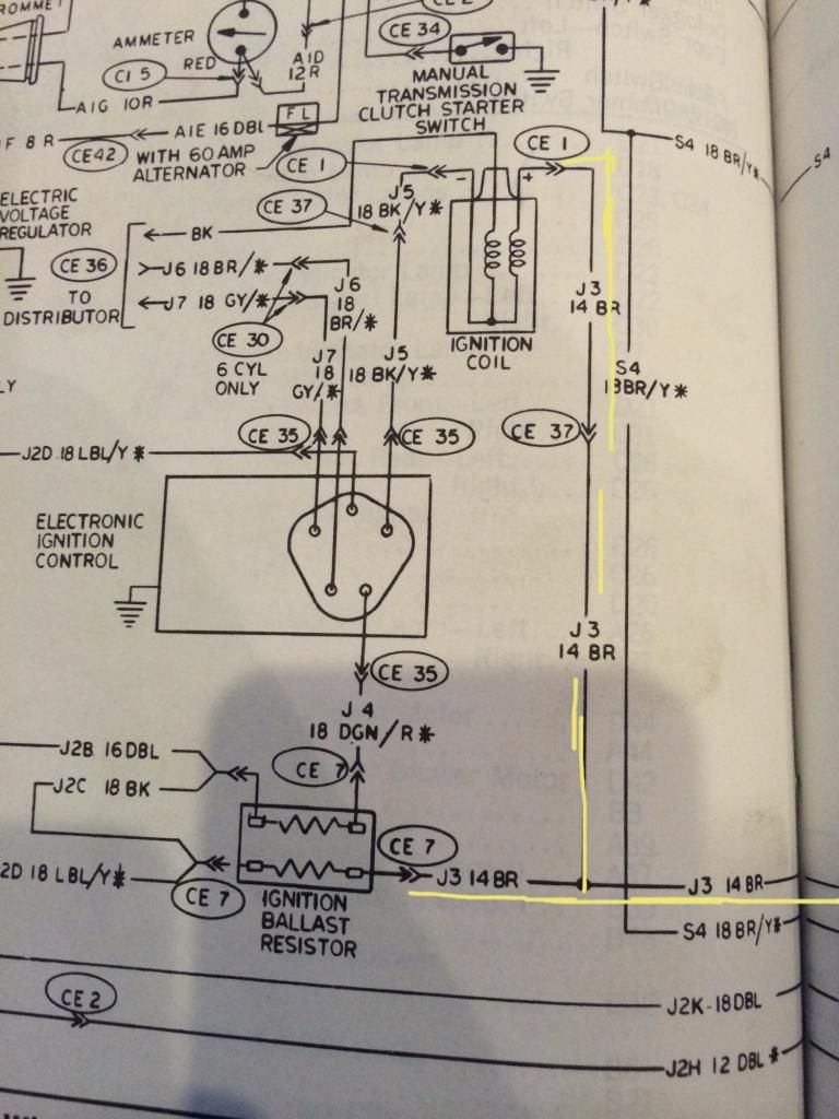
J3 wire (brown) feeds into the seatbelt interlock connecter and also splits off going to ignition ballast resistor and ignition coil positive (shown as J3 14 BR in the diagram):
M16 (20gauge Black) feeds into the seat belt & key in buzzer (which has been disconnected since I got the car), so that makes sense that there isn't continuity.

What about that brown coil/ballast wire though?
With the key out of the ignition and car in park, shouldn't I be getting continuity in the brown coil positive / ballast wire?
I figured out what the wires not showing continuity are.
J3 12gauge Brown and M16 20gauge Black.

J3 wire (brown) feeds into the seatbelt interlock connecter and also splits off going to ignition ballast resistor and ignition coil positive (shown as J3 14 BR in the diagram):

M16 (20gauge Black) feeds into the seat belt & key in buzzer (which has been disconnected since I got the car), so that makes sense that there isn't continuity.

What about that brown coil/ballast wire though?
With the key out of the ignition and car in park, shouldn't I be getting continuity in the brown coil positive / ballast wire?
67Dart273
Well-Known Member
The J3 is what is known as "IGN2" or the "ballast resistor bypass." It only goes one place "functionally".......from the switch, through the bulkhead, and to the ballast resistor terminal which connects to the coil+ terminal
The brown to the interlock is a branch but it's not in series. If you have not bypassed the two yellows in the interlock relay under the hook I would do so. Then, you can simply unplug the box under the dash
So far as the key buzzer I'd love to leave it disconnected / unplugged
The brown to the interlock is a branch but it's not in series. If you have not bypassed the two yellows in the interlock relay under the hook I would do so. Then, you can simply unplug the box under the dash
So far as the key buzzer I'd love to leave it disconnected / unplugged
The J3 is what is known as "IGN2" or the "ballast resistor bypass." It only goes one place "functionally".......from the switch, through the bulkhead, and to the ballast resistor terminal which connects to the coil+ terminal
The brown to the interlock is a branch but it's not in series. If you have not bypassed the two yellows in the interlock relay under the hook I would do so. Then, you can simply unplug the box under the dash
So far as the key buzzer I'd love to leave it disconnected / unplugged
Thanks for the info!
Yes, I have already bypassed the interlock relay by soldering the yellow wires.
Find any evidence of arcing to the firewall behind that ballast resistor ?
How about arcing to the bolt in the center of it ?
Nothing more than a small crack and/or water can cause them to do strange things.
I will have to take a look at the firewall. I did notice that there are cracks in the old ballast resistor by the terminals though:

taking one problem at a time, I thought I would recap what I have done up to this point.
The Scamp is my daily driver, so being without a car really sucks and has become very frustrating.
1. I re-wired the IGN1 or Ignition Run circuit that was previously burned up. I verified continuity in the new wiring.

2. I replaced the old ballast resistor with a new one. I hope I have this installed correctly, as I could not find a diagram or drawing stating the mounting position. I put it back the way the old one was (the "U" shaped cutout is on the right side, if you're looking at it head on).

3a. The ammeter was bypassed by joining the red and black wires under the dash, at the ammeter. The wires were routed back through the firewall and then connected with each other in the engine bay, as detailed in the MAD article. This wire is now connected at the starter relay with a fuseable link. Continuity was verified.
3b. The alternator output wire was also routed directly to the starter relay with a fuseable link connection. Continuity was verified.
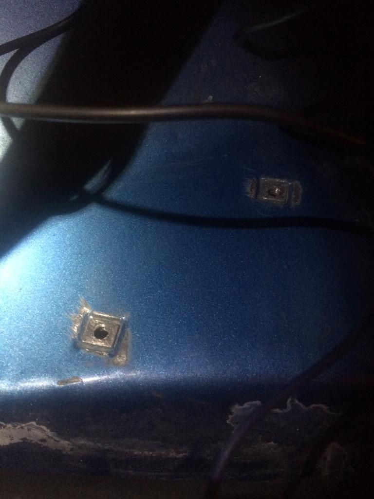
4. The voltage regulator ground was established, as it was not grounded before (possibly my initial problem). I removed the VR and filed the thick paint off of the screw flanges that mount the VR to the fender.
NOW, before I introduce power back into the system or hook anything up, what should my next course of action be?
-The battery is fully charged but, not hooked up (both terminals disconnected).
-The alternator is not hooked up to any circuit but, it is still in the vehicle.
-The Voltage Regulator is not hooked up the alternator
I hope someone can help me with how to continue from here...
I want to proceed cautiously to prevent causing any more damage.
The Scamp is my daily driver, so being without a car really sucks and has become very frustrating.
1. I re-wired the IGN1 or Ignition Run circuit that was previously burned up. I verified continuity in the new wiring.

2. I replaced the old ballast resistor with a new one. I hope I have this installed correctly, as I could not find a diagram or drawing stating the mounting position. I put it back the way the old one was (the "U" shaped cutout is on the right side, if you're looking at it head on).

3a. The ammeter was bypassed by joining the red and black wires under the dash, at the ammeter. The wires were routed back through the firewall and then connected with each other in the engine bay, as detailed in the MAD article. This wire is now connected at the starter relay with a fuseable link. Continuity was verified.
3b. The alternator output wire was also routed directly to the starter relay with a fuseable link connection. Continuity was verified.

4. The voltage regulator ground was established, as it was not grounded before (possibly my initial problem). I removed the VR and filed the thick paint off of the screw flanges that mount the VR to the fender.

NOW, before I introduce power back into the system or hook anything up, what should my next course of action be?
-The battery is fully charged but, not hooked up (both terminals disconnected).
-The alternator is not hooked up to any circuit but, it is still in the vehicle.
-The Voltage Regulator is not hooked up the alternator
I hope someone can help me with how to continue from here...
I want to proceed cautiously to prevent causing any more damage.
67Dart273
Well-Known Member
I think I addressed this earlier. "Come up with" a HEAVY 12V light bulb, "large" as you can rig up. One way is a headlight, (or a driving light lying around) another is a stop / tail with both filaments wired together.
Hook up everything except the battery ground cable. Ground one end of your "rigged" light to the block, and hook the other terminal to the battery NEG terminal. This will make a "light 'em up fuse" that will light up BRIGHT if there's a heavy load or short, and will protect ALL of the car's wiring against burning up.
If it lights, start finding out WHY. Make sure the hood lamp, trunk lamp, dome lamp, is all off. Make sure the key is off, any "hot" stuff like stereo or headlights. If you get everything "off" and it's still lit, pull the fuses one at a time.
If it's STILL lit, pull and tape off the alternator output wire. If it's STILL lit, you either left something turned on, or you have a short.
Now, if this checks out OK, pull your ECU connector loose, and unhook the + wire of the coil. Any light? Unplug the voltage regulator
Any light? Double check for anything (dome lights, heater, etc) turned on. Make sure everything is off except the key.
If it STILL lights, there might still be a load "under the hood," or you might have a short. The cluster gauges, and warning light (oil light, etc) will cause the test light to "come on" somewhat, and brightness will depend on "how big" the test light is.
Post back with results. Looks like you are making progress
Mad Dart
Nothing to see Here!
I think I addressed this earlier. "Come up with" a HEAVY 12V light bulb, "large" as you can rig up. One way is a headlight, (or a driving light lying around) another is a stop / tail with both filaments wired together.
Hook up everything except the battery ground cable. Ground one end of your "rigged" light to the block, and hook the other terminal to the battery NEG terminal. This will make a "light 'em up fuse" that will light up BRIGHT if there's a heavy load or short, and will protect ALL of the car's wiring against burning up.
If it lights, start finding out WHY. Make sure the hood lamp, trunk lamp, dome lamp, is all off. Make sure the key is off, any "hot" stuff like stereo or headlights. If you get everything "off" and it's still lit, pull the fuses one at a time.
If it's STILL lit, pull and tape off the alternator output wire. If it's STILL lit, you either left something turned on, or you have a short.
Now, if this checks out OK, pull your ECU connector loose, and unhook the + wire of the coil. Any light? Unplug the voltage regulator
Any light? Double check for anything (dome lights, heater, etc) turned on. Make sure everything is off except the key.
If it STILL lights, there might still be a load "under the hood," or you might have a short. The cluster gauges, and warning light (oil light, etc) will cause the test light to "come on" somewhat, and brightness will depend on "how big" the test light is.
Post back with results. Looks like you are making progress
I learned me something today! Good stuff.
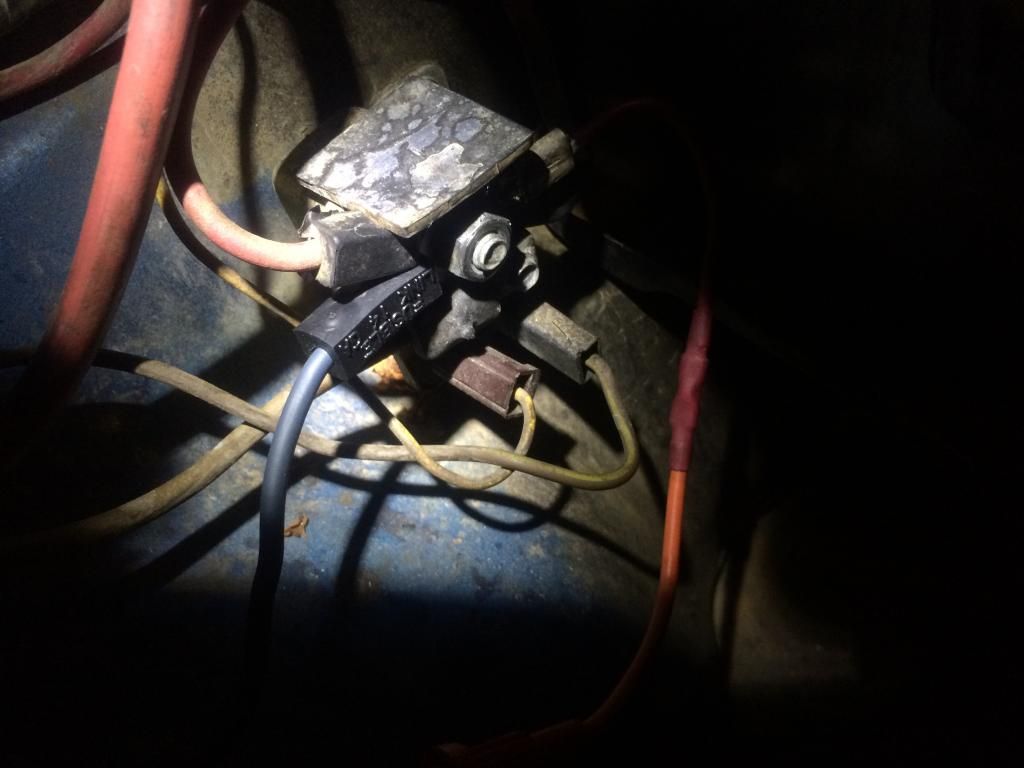
Ah yes. I remember you mentioning the rigged test lamp. I made one, twisted a lead together on the two terminals and connected that to the battery negative terminal. I used the ground terminal on the light and connected that to the block ground (green clip in photo).

I followed your directions, step by step, and here are the results.
I made sure everything was off, doors shut, and no key ignition. After hooking everything up - I got no light.
Pulled ECU Connector loose - no light.

Disconnected the (brown) Coil positive wire - no light.

Pulled the Voltage Regulator connector - No light.
Double checked and made sure nothing was on.
Made sure everything was off except the key.... no light.
I noticed you said at the beginning to make sure the key was off and at the final step, you mentioned to have the key on. Both ways produced no light.
What is weird, and I'm not sure if this was supposed to happen with the test lamp rig, but with everything hooked back up, test light still hooked up - I put the key in "on", none of the gauges worked and no dash lights came on....and the test lamp did not light.
I know when things were working normal, the oil light would glow red before starting the car and the temp / fuel gauges would move and were functioning correctly.
This doesn't happen now.
Not sure if that's related, but I thought it was worth mentioning.
Does everything sound correct up to this point?

I followed your directions, step by step, and here are the results.
I made sure everything was off, doors shut, and no key ignition. After hooking everything up - I got no light.
Pulled ECU Connector loose - no light.

Disconnected the (brown) Coil positive wire - no light.

Pulled the Voltage Regulator connector - No light.

Double checked and made sure nothing was on.
Made sure everything was off except the key.... no light.
I noticed you said at the beginning to make sure the key was off and at the final step, you mentioned to have the key on. Both ways produced no light.
What is weird, and I'm not sure if this was supposed to happen with the test lamp rig, but with everything hooked back up, test light still hooked up - I put the key in "on", none of the gauges worked and no dash lights came on....and the test lamp did not light.
I know when things were working normal, the oil light would glow red before starting the car and the temp / fuel gauges would move and were functioning correctly.
This doesn't happen now.
Not sure if that's related, but I thought it was worth mentioning.
Does everything sound correct up to this point?
67Dart273
Well-Known Member
At this point you have an "open" or "disconnect." You don't seem to be getting power to the load
Here's how this light thing works. Imagine in your mind a "loop" of a circuit, and you need something that draws (for example) "a bit" "a bit more" and "a lot" of current.
Let's imagine we have a "normal" working car and that we use our headlamp We turn the key to run, and the lamp will light "at some brightness"
What we have is a path...........battery positive.......through harness to ignition switch.......through harness to the cluster, warning lamps, ignition system, and voltage regulator..............to car ground.........up through our "test lamp" ..........and back to battery negative.
As you switch on more and more "stuff" the test lamp will light more and more brightly. If you switch on a REALLY large load, like headlights and or heater blower, it will REALLY start to light.
So you must constantly keep in mind "what you are doing" and "what you have on."
The purpose is to protect the car wiring, and allow you to find stuff with no worries of burning "junk" up.
==============================
But what you are describing here, sounds like NOTHING is drawing current, so now you have to find out WHY. You probably "fried" something else when you smoked things.
Start at the connector for the ignition switch. If you have trouble with the diagram, post back. Find the "accessory" and "ignition run" (usually says "IGN 1") and see if you have power there with the key "in run."
If not, check the power wire coming INTO the key.
Thanks for the thorough explanation.
I quickly checked this morning and you were exactly right.
The red wire in the ignition switch harness (I believe this is power), was completely fried. I mean, it burned out the damn connecter.
Seems logical for me to START with where that wire ENDS, which is the key ignition switch, and work my way back to the burned connector. Especially since I checked and I have continuity from the ignition switch harness to the bulkhead harness.
67Dart273
Well-Known Member
Good progress. I hope by now you have read the MADD article. This points out the problems with the bulkhead connector. Check it thoroughly. Now that you've had a BAD short, one that fries wires, there's been a LOT of current going "back and forth" (figure o' speech) through there.
Frankly, at this point you should consider dropping the column, pulling the cluster, and stripping the under--dash harness out, and at least PARTIALLY untaping it and inspecting it. There is probably damage----damage that can cause shorts later on if not now.
Frankly, at this point you should consider dropping the column, pulling the cluster, and stripping the under--dash harness out, and at least PARTIALLY untaping it and inspecting it. There is probably damage----damage that can cause shorts later on if not now.
Mad Dart
Nothing to see Here!
Did you make sure that Headlamp/Test Lamp works "Lights Up" when hooked up to + & - , before doing the testing?
Good progress. I hope by now you have read the MADD article. This points out the problems with the bulkhead connector. Check it thoroughly. Now that you've had a BAD short, one that fries wires, there's been a LOT of current going "back and forth" (figure o' speech) through there.
Frankly, at this point you should consider dropping the column, pulling the cluster, and stripping the under--dash harness out, and at least PARTIALLY untaping it and inspecting it. There is probably damage----damage that can cause shorts later on if not now.
That was my exact thought also. No use in just fixing one wire when it could have very easily fused or damaged a whole bunch of them...that I can't even see.
I'll do just like I did with the ignition circuit. That is, pull the whole thing, lay it out, un-tape it, and just go over all the wires / connections. There's no telling what surprises I might find! Ha!
It might be a while but, I'll post my progress once I'm back to a point where I'm ready to re-test using the lamp method.
Did you make sure that Headlamp/Test Lamp works "Lights Up" when hooked up to + & - , before doing the testing?
Yes sir! Mainly because I wasn't sure which of the 3 posts was the actual ground wire.
")
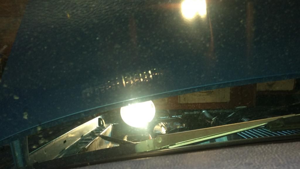
I just wanted to quickly share with you all how well 67Dart273's rigged test lamp method works.
Believe me, if you follow his directions, step by step, and can comprehend what he's telling you, then you'll most likely be successful at whatever electrical problem you're facing.
I hooked up my test lamp. Battery Pos. (+) cable was hooked up to the battery, then one lead coming off the headlamp ground terminal was hooked up the engine block ground. The other lead was hooked up the one of the other terminals of the headlamp (i just picked one) and clipped to the Battery Neg. (-) terminal. The battery negative cable from your car is NOT hooked up.

Now,
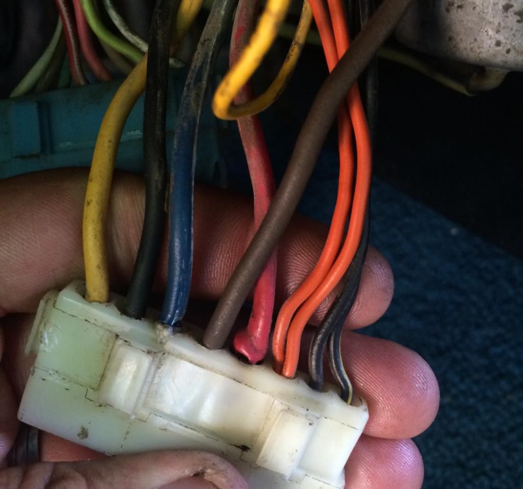
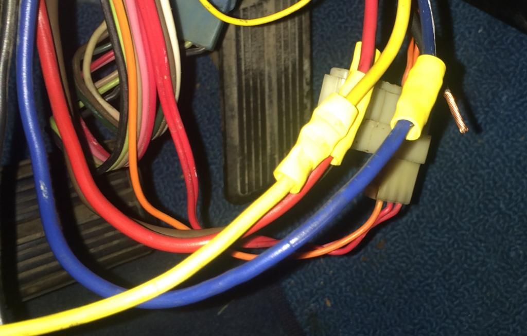
I know that my "problem" is somewhere in the path from the ignition wiring from the steering column....to.....the under dash wiring. Seeing as these white connectors previously gave me trouble on the engine side of the car, I opted to get rid of it altogether (as seen below). I made temporary crimp connections from the under dash wire harness to the steering column wire harness, and tested continuity of each wire.
To my surprise, all but one wire showed continuity. The thicker 12guage Black wire. My wiring diagram shows this wire going from the steering column, to the fuse box, and branching off onto the wiper motor.
I decided to try out my test lamp to confirm I had a short and it worked perfect.
I stuck the key in, turned it to the back position and "no light".
I then went back to the BEGINNING position (where you first put the key in) and clicked the key to the 1st position (I believe this is ACC?), again.... NO LIGHT.
I clicked it over to the next position, the one that is before cranking the car over, (I believe this is RUN) and boom - there was the light in my face.
So now I just need a little clarification of the actual key positions vs. the wire diagram so I can chase the short down that is in the dash harness.
Here is how the service manual lays this out & here is how I'm interpreting it:
My interpretation:
1st Position - ACC
2nd Position - RUN
3rd Position - START
Here is the wire diagram:

Looks like we're (....or "I'm"), one step closer to getting this sorted out! Thanks for your help!
Believe me, if you follow his directions, step by step, and can comprehend what he's telling you, then you'll most likely be successful at whatever electrical problem you're facing.
I hooked up my test lamp. Battery Pos. (+) cable was hooked up to the battery, then one lead coming off the headlamp ground terminal was hooked up the engine block ground. The other lead was hooked up the one of the other terminals of the headlamp (i just picked one) and clipped to the Battery Neg. (-) terminal. The battery negative cable from your car is NOT hooked up.

Now,
I know that my "problem" is somewhere in the path from the ignition wiring from the steering column....to.....the under dash wiring. Seeing as these white connectors previously gave me trouble on the engine side of the car, I opted to get rid of it altogether (as seen below). I made temporary crimp connections from the under dash wire harness to the steering column wire harness, and tested continuity of each wire.

To my surprise, all but one wire showed continuity. The thicker 12guage Black wire. My wiring diagram shows this wire going from the steering column, to the fuse box, and branching off onto the wiper motor.
I decided to try out my test lamp to confirm I had a short and it worked perfect.
I stuck the key in, turned it to the back position and "no light".
I then went back to the BEGINNING position (where you first put the key in) and clicked the key to the 1st position (I believe this is ACC?), again.... NO LIGHT.
I clicked it over to the next position, the one that is before cranking the car over, (I believe this is RUN) and boom - there was the light in my face.

So now I just need a little clarification of the actual key positions vs. the wire diagram so I can chase the short down that is in the dash harness.
Here is how the service manual lays this out & here is how I'm interpreting it:
My interpretation:
1st Position - ACC
2nd Position - RUN
3rd Position - START
Here is the wire diagram:

Looks like we're (....or "I'm"), one step closer to getting this sorted out! Thanks for your help!
superchargeddrt
Well-Known Member
I would say that what you are seeing is normal. In the accessory position the light is not on because nothing else is on in the car and you do not have any shorts, this is GOOD. In the run position again you don"t have anything on that's drawing current and again no shorts. When you move the key to the start (cranking) position the the starter is in circuit and trying to draw a lot of current and therefore the lamp will light, THIS IS NORMAL. It' looks to me like you're ready to give it a try. Good Luck
When you move the key to the start (cranking) position the the starter is in circuit and trying to draw a lot of current and therefore the lamp will light, THIS IS NORMAL....
Thank you. I understand what you mean however, I may have mixed up my wording.
I actually did not get the key to the final "cranking" position. I only got up to the position before the cranking, saw the light, and stopped there.
If I understand correctly, a short in this position (what I'm assuming is RUN), with the lamp lighting up, makes sense because the black wire is still "open" from the steering column to the dash harness.
clear as mud?
67Dart273
Well-Known Member
You are on the right track. That diagram is not drawn exactly correctly. The brown and the yellow are not actually connected to the same contacts in the switch. They are in fact separate "switches" within the switch "housing." They do both energize in "start."
The reason they must be separate is because ............picture in your mind..........
The brown is electrically connected to the coil. With the key back in "run" and the engine running, the coil gets voltage through the ballast, "less than" 12V So the brown "has" this same voltage on that wire
Now if the brown and yellow were actually interconnected, this coil voltage would "back feed" over to the yellow and "attempt" to power up the starter relay!!!!
Now, on a car new enough to have a clutch switch, or an automatic with a neutral safety switch, this could not happen, until you either pressed in the clutch, LOL, or had the car in park / neutral
Even if there's not enough power there to pull in the starter relay, it still will "load down" the coil circuit.
Ok I had some time to try and get this sorted out.
Remember: I was not getting continuity in the 12g Black wire from the dash side ignition harness.
Before pulling the cluster, I checked continuity on the 12g Black wire and got nothing. No light.
I dropped the column, pulled the cluster, unwrapped the tape and inspected the wires in the harness.
I remember someone mentioning that a screw that holds the cluster in place, pierced their wires so, I decided to check for this.
I removed the screws, re-checked continuity, and had a light! It wasnt as bright as the others, so I knew I still had work to do
I first found the welded splice for the ammeter feed and that looked/tested ok. Taped it back up.
I then found the 2nd welded splice, which my 12g Black ignition wire is part of.
It was spliced to a 12g Pink wire that goes to the wiper switch. That was ok, although the connection at the wiper switch was a little loose. I taped it back up and fixed the connection at the switch.
I checked the ohms in this particular circuit since it only seems to go 2 places (ignition switch to wiper switch and fuse box).
1. Ignition connector (12g Black wire) to Fuse box result: .001 Ω
2. Ignition connector (12g Black wire) to connection at wiper switch (12g Pink wire) result: .001 Ω
At this point here is the only thing I can think of whats going on:
A. The black or pink wire was pierced by the mounting screw for the cluster.
B. There is still a loose connection SOMEWHERE in the bulkhead connector. I studied the wiring diagram and the 12g Black wire for the ignition does not go to the bulkhead connector. It only goes to the wiper switch and the fuse box. Could this wire be inline with another one I'm just not seeing?
Im ready to button this all up and start re-testing, either with the headlight and/or the inline fuse test methods.
What are your thoughts?
67Dart273
Well-Known Member
No, the MAD simplified diagram is fairly accurate
The "path" is this
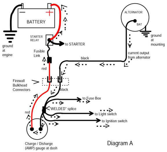
From battery, through bulkhead on RED
to and through ammeter, out ammeter on BLACK and on to SPLICE
SPLICE branches off and feeds
IGNITION SWITCH
OUT through bulkhead to ALTERNATOR (black)
and to fuse panel "hot" buss
and to wiper switch, headlight switch, etc
From ignition switch you have several outputs
"ignition run"
start
bypass
and ACCESSORY (black)
This big black wire comes FROM the ignitions switch and TO the accessory buss in the fuse box
The SECOND buss in the fuse panel is your "HOT" buss and this comes direct from the splice to that fuse buss.
There are only so many places to "lose" it assuming no one has cut wires
RED terminal coming in through the bulkhead from fuse link
AMMETER terminals
WELDED SPLICE
Going back out to the alternator FROM the splice, the only thing between is the BLACK terminal in the bulkhead
Branching off from the WELDED SPLICE are the
IGNITION SWITCH and or CONNECTOR at the switch
Connections at the FUSE PANEL
WIPER feed in some years
HOT fuse buss feed
HEADLIGHT power feed
=============================================================================
What is not shown in the diagram below:
Ignition switch and feed from switch to "switched" accessory buss in fuse panel
They do not show the wiper feed, I'd have to check that. Yours comes off the splice?
http://www.madelectrical.com/electricaltech/amp-gauges.shtml
The "path" is this
From battery, through bulkhead on RED
to and through ammeter, out ammeter on BLACK and on to SPLICE
SPLICE branches off and feeds
IGNITION SWITCH
OUT through bulkhead to ALTERNATOR (black)
and to fuse panel "hot" buss
and to wiper switch, headlight switch, etc
From ignition switch you have several outputs
"ignition run"
start
bypass
and ACCESSORY (black)
This big black wire comes FROM the ignitions switch and TO the accessory buss in the fuse box
The SECOND buss in the fuse panel is your "HOT" buss and this comes direct from the splice to that fuse buss.
There are only so many places to "lose" it assuming no one has cut wires
RED terminal coming in through the bulkhead from fuse link
AMMETER terminals
WELDED SPLICE
Going back out to the alternator FROM the splice, the only thing between is the BLACK terminal in the bulkhead
Branching off from the WELDED SPLICE are the
IGNITION SWITCH and or CONNECTOR at the switch
Connections at the FUSE PANEL
WIPER feed in some years
HOT fuse buss feed
HEADLIGHT power feed
=============================================================================
What is not shown in the diagram below:
Ignition switch and feed from switch to "switched" accessory buss in fuse panel
They do not show the wiper feed, I'd have to check that. Yours comes off the splice?
http://www.madelectrical.com/electricaltech/amp-gauges.shtml
-


