The Great Pumpkin - '71 Duster

-
I like your approach to refurbishing/upgrades. Nice detailed pics. Very smart to start with a car with good body/paint.

subscribed

-Chris

Thanks Chris, I appreciate your comments. I was glad to read that you recognize an overall approach, it's one of the most important aspects of this project for me. It influences just about every decision I make.

My main goal with this car is to keep the basic format of the original build but to maximize its potential with thoughtful parts choices and better execution. How's that for a mission statement?

Bottom line though is that it's rewarding to know that there is interest in what I'm doing!

More to come.
 
I replaced the balancer a little while ago but I'm just getting around to getting the pics up.

The balancer that was on the engine was looking worn out and after I removed it, I realized that it actually was in fact totally beat. The rubber isolator was shot. I wiggled it off with my hands after the bolt came out, no puller needed. Probably slipping.

I got a Pioneer internal balance unit from Summit. Initially, I was going to get it from CNC Motorsports who had them cheaper even with shipping. I got Summit to price match it though and got free shipping on the order so it worked out OK. The part was on back order so I had to wait a bit. No big deal, car is in pieces.

Thought I'd also write a little about the balncer installer tool here as well in case you are unfamiliar with one. I recommend using the correct tool for this job. When I was working as a tech, I used to borrow a balancer installer tool from the guy across from me so I never got my own. Some guys would put the unit on loosely and cinch it down using a gun on the crank bolt. I would always make it a point to use the tool though. I thought the gun method posed too much of a risk. So of course now I need the tool but I'm S.O.L. 'cause i have no one to borrow it from. I finally broke down and got one - a cheap one from Summit that works well.

Pioneer wants you to measure the I.D. of the balancer hub and compare it to the O.D. of the crank snout to make sure there isn't too much or too little interference. They give you a spec to shoot for and tell you to machine the I.D. of the hub for correct fit. I threw caution to the wind, voided my warranty and installed it without much fanfare. Seemed to go on with the right amount of interference. Can't be any worse than what was on there.

The Pioneer balancer is a nice-looking product, especially with the cool-guy engraved timing marks. I learned about the part because Myron (Locomotion) recommends them every time a "what balancer" thread comes up. Seeing that he's pretty successful at what he does, I would trust the things he uses to be top notch parts.

OK, on to the pics. Here's Ye Olde 340 balancer that was replaced.
IMG_9589800x534_zps4ad6b3f9.jpg


Rubber isolator ring was toast. I've seen worse but it was time for a replacement.
IMG_9706800x600_zps14b3caea.jpg


New part.
IMG_9592800x534_zps7ddafee0.jpg


OOOOOOOHHHH, shiny.
IMG_9593800x534_zpsdbed9ff1.jpg


Installation tool in action. Much easier to do this job with the radiator out.
IMG_9704800x600_zpsd17ca5b9.jpg


Installed.
IMG_9738800x600_zps0d34f594.jpg


Note engraved timing marks. No more White Out.
IMG_9739800x600_zps52ac9f14.jpg


Been working on other things as well. Got most of the trans cooler lines plumbed. I hope to button up the front of the engine bay soon. Also working on mounting my seats. I need to figure out how to adapt the S/S seat brackets to my seats and to the floor since they don't exactly line up.

More to come.
 
So I got a big job done which was re-doing the transmission cooler lines and installing a new B&M Supercooler. I was kind of dreading doing the lines without a lift. It wasn't that bad actually and went a little bit better than I expected it would. I guess I might be getting a little bit better at plumbing.

I'm not sure if the lines that were on there originally were OE or not. They were 5/16" steel with brass fittings. They did not run through the radiator but went to a small trans cooler that was lashed to the the rad. core with those cheesy zip ties. The hard lines were connected to the cooler with rubber hoses and clamps that went under the radiator support and up to the cooler. The rubber hoses were leaking - enough to usually see a small red puddle under the front of the car the day after I drove it. Time for a change.

I like AN type fittings so I went with 3/8" aluminum tubing and -6 AN fittings. The cooler taps on the case are 1/8" NPT so I needed 1/8NPT to -6 adapter fittings to connect to the hard line tube nuts. I wanted the lines to go through the radiator support so I used 90 degree bulkhead fittings. The cooler was plumbed with hard line to the bulkheads and I used push lock hose to connect the bulkhead fittings to the hard lines.

I ran the lines up the left side frame rail like they were initially. I had to route them around the exhaust and over the brake line block. I used heat shield/tape where the lines come close to the header tube. I got some fancy line clamps to keep them neat. Near the front of the hard lines I used a dual line clamp I had in my bolt box from work. I took many cooler lines out when I was wrenching and I always seemed to end up with one or two of these. They work good and are tough. I tapped it for a 5/16" bolt and secured to the front frame.

When I measured the tubing to see how much I would need, I miscalculated and ended up short. I decided that I could use some push lock hose for an easy disconnect should I need it. I think it also allows a little flex. The one draw back to this style of plumbing is all the fittings involved. On the trans cooler lines alone I have two pipe to AN adapters, 8 sets of tube nuts and sleeves, 4 hose ends, two bulkhead fittings and two -6 couplers. That's like $200 in fittings. Makes me a little queasy to think about but it looks bitchin'. :D

I also took a few pics detailing a the flaring process when using 37 degree AN type fittings. Its a single flare but requires a specific tool to do the job. I have a Ridgid 37 degree flaring tool that makes perfect flares every time. To cut the tube, I use a Blue Point tubing cutter. Some guys say not to use tubing cutters because it work hardens the material but it works well for me. I keep the roller blade lubed which helps. I use a few different benders to make the tubing - an Imperial Eastman 3/8" lever bender and a universal one I got from Sears. They both have their uses and switch back and forth when needed.

OK, on to the pics.

Here's a piece of tubing cut and ready to flare.
IMG_9719800x534_zps09d6692d.jpg


This is the B.P. tubing cutter.
IMG_9720800x534_zps618f9c58.jpg


Here's the Ridgid flaring tool. Aluminum tubing is very soft so the tool can be used like this but sometimes I stick it in a vice which makes it a little easier.
IMG_9721800x534_zpsd3ed10d0.jpg


Perfect flare every time.
IMG_9718800x534_zpsfe4b73d1.jpg


Here's the new ones made up next to the old ones for comparison.
IMG_9722800x534_zpsa465cbb2.jpg


Detail of the heat shielding stuff.
IMG_9723800x534_zpsca13233f.jpg


Lines installed in the car. Couldn't get pics of where the lines attach to the case, there's not enough room and poor sight lines.
IMG_9729800x534_zps6976cb97.jpg


Here's the hard lines from the cooler to the bulkhead and the push lock hose to the hard lines. This custom stuff sure can take up a lot of time and money but I'm happy with how it turned out.
IMG_9734800x534_zpscb1f4e63.jpg


More to come.
 
Moving along with the front of the car. I finally finished the install of the aluminum bumper brackets I got back in March. I had done the left right when I got them but not the right until yesterday.

I got the brackets from a racer out in MI named Jody Babcock who goes by jbmopars on here. He is a fabricator and he made these up for his own project. I guess he had a spare set on hand so he put 'em up for sale and I picked 'em up. They are really cool parts and per him save around 8 -9 lbs on the front of the car. They bolt right up like the stock pieces.

They took a little doing to put in but nothing real major. I knew I had to do one side at a time to keep the position of the bumper in relatively the same spot. Plus, the outside bracket was not drilled for the fender support rod so I needed to verify correct positioning before final assembly.

Before I removed the original ones, I measured the distance of the lower fender lip to the inner frame rail for reference. I also scribed reference lines where the edge of the brackets were so they would wind up back in the same spot. Once the new brackets were in and they looked OK, I drilled the hole for the support rod where I thought it should go. The procedure worked like a charm and the fender lip was in the same spot.

Once the job had begun, I noticed the bumper looked a little crooked. I measured the distance from the back of the bumper to the character line on the front of the fender and they were in fact off side-to-side a little. After the swap, the bumper actually ended up tucked a little closer to the filler panel and slightly more even from side to side. I'm still not 100% sure if it's right though but its close. I think it might have to be adjusted again when it's back on all four wheels and sitting at ride height.

Here's the brackets as received from Jody.
IMG_9023800x534_zps1a064616.jpg


Here's the original bumper brackets in place before removal. You can kind of see where I scribed the lines for positioning. The milk crate and wood blocks were for support and to keep the bumper in relatively the same place while the new brackets were installed.

The wetness you see are the fasteners being soaked with PB Blaster prior to taking them out. Before they are reinstalled, they were subjected to the rigorous Great Pumpkin 4 step fastener restoration process; remove, wire wheel loose grease/dirt/scale/, dump in Evaporust overnight, rinse with water, wire wheel again, coat with ECS Rust Prevention Magic and re-install. Takes forever but looks nice.
IMG_9025800x534_zps3d3428d5.jpg


Support for the bumper while the brackets are out.
IMG_9027800x534_zps0037263a.jpg


Here's the aluminum bracket installed on the left side. This is after the fender support rod position was finalized.
IMG_9746800x534_zps1a8f4e74.jpg


Here's the right side. If you look at this pic and the previous one, you can see the witness mark where the bracket bolts to the back of the bumper; that's where the old ones were and why the aluminum ones needed to be adjusted. This is also why you can't drill the support rod hole until you get the bumper sitting where you want it. The right fender ended up slightly further out than the left. Again, I may have to re-adjust when I get the car back on the ground but it's close enough for now.
IMG_9747800x534_zps6c49bb73.jpg


Here's the old stamped steel clunkers.
IMG_9749800x534_zps9a9e8050.jpg


More to come.
 
Nice job on the lines. Its not easy making those bends that clean !
 
I also got the coolant catch can in place. It's an RCI brand I got at SK Speed here on Long Island. Frankly, it looks sort of crappy when you take it out of the box. The fittings are epoxied in and the whole thing looks genuinely rough. I had the kid who helped me out look through a few of them and pick the best one. Its much better than the one it replaced though.

The one thing I don't like about the RCI can it is that I can't see how much coolant is actually in there. Seems like a lot of the aftermarket ones are like this, whatever the brand or material they're made out of. On most cars, the catch cans are opaque so you can see the coolant inside. There's also usually a fill line for reference when you're adding coolant to the system but not so on this one since it's black. I'll put some in there when I re-fill the system.

The Griffin radiator I got has the overflow spout on the left instead of on the right where it originally was on the old radiator. To mount the new catch can, I made a bracket out of aluminum channel and used existing holes in the radiator support to fasten it down.

The new radiator also required the hoses to be shorted since its much closer to the engine than the original one so that's done. I did try to use some late model spring clamps I had for a cleaner look but it ended up being easier to re-use the worm clamps. I'm not a huge fan of worm clamps - they look cheap to me. Regardless, I cleaned up the old hose clamps (I'm weird like that) and put 'em back on.

I have to say I'm getting a little tired of making these little custom brackets for everything. Good or bad, I am sort of particular about how I want them to look and function which ends up taking a lot of time and effort for very little return. I suppose that's the definition of labor of love.

Anyway, the catch can is mounted up. No new holes were drilled in the mounting of this puke can.

So here is the gunked up old one. Not so much, right?
IMG_9753800x534_zps8950f937.jpg


The gray things were used as spacers. I have no idea what they are from or for.
IMG_9754800x534_zps71ef1b75.jpg


Here's the RCI catch can in place.
IMG_9750_zpse3bf140e.jpg


And the mounting bracket.
IMG_9752_zpsa7abc7fe.jpg


More to come.
 
Cleared two pretty big hurdles today. I finally got my driver's seat mounted and POR 15'd the floors and trunk.

Feels like I've been trying to figure out the seat situation for months. During the spring, I decided to ditch the big and heavy old bench seat. That behemoth literally weighs 100lbs so I'm stoked to be rid of all that dead weight. I had two sets of seats to choose from but I'll give the story on the ones I picked first. My old boss (the owner of the dealership I used to work at) drove around a beat up, old '85 Jeep Scrambler. He had taken the OE seats out for some more modern ones and left the old ones sitting in the prep area. They caught my eye one day and I did a double take because they look really similar to Dodge A100 van seats (except for the high back of course). I asked what he was doing with them and he told me I could take 'em. So I did.

I got the seats some time last year, can't remember exactly when. I didn't know what I was going to do with them but I liked 'em. The other seats I have are a set of NOS A100 van seats. I've had them for a long time, since the 90s. So now the bench seat is out and I keep looking at both these seats side by side and thinking that I wanted to use one or the other in the Duster. After a lot of going back and forth trying to decide which ones to use (yeah, I got uptown problems) I ended up picking the Jeep seats.

There were a few reasons I didn't go with the van seats. First, they're uncomfortable. Not in a luxury sense but the just do not feel natural. Whenever I'd sit in them, it felt like I was crunched up. For whatever reason, the Jeep seats just felt better to me. Second, the van seats don't really belong in a 70s car. They're clearly an early 60s design and in my mind don't fit aesthetically. You could also argue that the Jeep seats don't look 'correct' either but they look more right to me. I am a stickler for historical details but for whatever reason, putting in seats from an '80s Jeep didn't bother me as much as putting a square 60s seat in a 70s car. Maybe its the fact that the A100 seats are more sacred and probably deserve to be in the right car. Since the two seats are in fact so similar, I did wind up using a set of repro. A990 seat brackets to mount the Jeep seats. Best of both worlds I guess. Or worst.

What's surprising is how similar the Jeep seats are to the A100s. Save for the high back of the Jeep seats, they're almost dimensionally the same. Both are fixed back and curiously the Jeep seats actually weigh less. When I got them, they still had the original, faded, weather-resistant type upholstery on so that had to go. I found a company on Ebay that makes reproduction seat covers in black vinyl that would be a close enough match to my existing interior so I ordered a set.

The main issue I had to resolve is the difference in mounting points between the bottom of the seat, the brackets and the floor pan. I wanted to use the original mounting points if possible but it wasn't gonna happen using components that were never designed to be used in a '71 Duster.

The Jeep seat frames are about two inches wider than the van seat frames but the seats are still basically the same width. To make it work, I had to drill and tap two new holes in the bottom of the Jeep seat frame to mount the seat to the brackets. Then, I drilled extra holes in the tops of the brackets to facilitate mounting them to the floor because the position of the original holes put the bottoms of the brackets too far apart. There is an offset between the top and bottom mounting holes on the brackets which complicates things further. Today seemed to be the day though so I hunkered down and got it done. Took a lot of measuring and head scratching but I'm happy with how it came out.

The seats are now non-adjustable when mounted to the A100 seat brackets. After it was all bolted down, I put the steering wheel in place to make sure the position of the seat was good. I read up on proper positioning and I did pretty well with it.

Next, I put the shifter in to see if it would end up in the same place but it looks like I'm going to have to move it back from where it was. I may make a simpler bracket to replace the big, clunky aluminum box that's under it now. Not sure yet.

After the shifter, I will need to do the passenger side seat. There's a little more offset in the floor from the trans tunnel to the sill as opposed to the left side so I hope it doesn't turn into another project to get it in the right position. It's not as critical as the driver's seat though.Next steps are new upholstery and deciding whether to weld in some braces for the floor or not.

The second thing I got finished over the weekend was sealing the floor pans and trunk with POR 15. The floors and trunk in this car are really solid but I want to keep it that way going forward. I slathered on the POR 15 to seal up the metal for good. Not that the car is going to be out in the rain or snow all the time but moisture has a way of getting into places its not supposed to here on the east coast. I plan to keep this car so whatever I can do to stave off the tin worm is worthwhile and POR 15 is cheap insurance.

When the seats come back out for the new covers, I'm gonna put down some Thermo Tec sound deadener/heat shield stuff and install the new carpet I got at Carlisle last year. Plus, I have to finish up the remainder of the wiring under the dash for the gauges and it will be much easier to do without the front seats in the way.

So here's the seat after being mocked up. I checked the driver position with the steering wheel on and stuck the shifter where I thought it should be. I also checked how well I could reach and actuate the the pedals in relation to the seat and it seems good. There is plenty of room overhead.
IMG_9756800x534_zps6b089875.jpg


Here's a a pic of where the shifter will end up. Its slightly farther back from where it was, I hope the cable is long enough. There used to be a bench seat in this car. Before it got the heave-ho, the back of the shifter was jammed up to the front of the bench.
IMG_9757800x534_zps298f1e24.jpg


Here's are a before and after shot of the spare tire well in the trunk. There was some surface scale but not rot through. It was a PITA to clean up back there. Something sticky spilled and was rolling around leaving black, sticky trails and drips all over the trunk. I used POR 15 Marine Clean and a soft brush to get the gunk off, then POR 15 Metal Ready before I laid down the paint. It's a little glossy but I'm not real concerned. Looks better than it did with all the sticky crap.
IMG_9643_zpsed0f8344.jpg


This is after a lot of cleaning and the POR 15 treatment. My hands are still wrinkled.
IMG_9755800x534_zps8429b528.jpg


More to come.
 
looking good. are you going to make/modify a console or go bare shifter?

Just the shifter, no accoutrements.

And the more I look at it, the more I wanna toss that mounting box and just make a simple riser bracket. I like where it is right now though, it's just right so whatever I come up with, it will end up at the same height.
 
Just the shifter, no accoutrements.

And the more I look at it, the more I wanna toss that mounting box and just make a simple riser bracket. I like where it is right now though, it's just right so whatever I come up with, it will end up at the same height.

how about something similar to the seat bracket?
 
Did some more stuff over the last couple days but didn't really accomplish a whole lot. I guess that's how it goes sometimes.

First thing I tried to do was make a new riser bracket for the shifter. Unfortunately it didn't exactly come out the way I thought it would. I wanted it to run parallel to the trans tunnel. The problem is the mounting holes for the shifter are 2 5/8" apart but I only had 2" flat stock so it had to go perpendicular. I guess I could have found some better stock but cutting it down is a pain and I didn't feel like going to find something. So I bent up two strips of flat stock to bolt the bottom plate to and set it on the trans tunnel. It looked ridiculous. I re-thought it and decided to keep the aluminum box I already had and modify it.

Whoever made the box did a decent job, the TIG welds are good. Originally it had flat stock welded to the bottom that stuck out on each side for tabs. There were machined aluminum blocks underneath those that mirrored the shape of the trans tunnel so the box could be mounted upright and solid. They bolted the tabs to the blocks then drove self tapping screws through the blocks into the floor to hold it down.

Due to the new new seat position, the shifter needed to be moved back a little for best fit. Since the shape of the tunnel is different in certain spots the box wouldn't mount solid farther back. The solution was to cut the old tabs off the bottom of the box and then clean up the welds so the bottom was smooth. I didn't finish it but I'm just gonna get some aluminum angle and bolt it to the front and back of the box rather than on the sides, then bolt it to the top of the tunnel. Should be easier to deal with and less holes to drill.

I've posted this picture previously but it shows what the shifter riser box bracket thing looked like before I modified it. You can see the tabs and the aluminum blocks with the self-tapping screws.
IMG_9757800x534_zps298f1e24.jpg


Here's a pic of the modified bracket. I painted it before it was modified so it's gonna have to get sprayed again. I might use a texture paint next time.
IMG_9782800x534_zps96957da6.jpg


This was the horrendous bracket I made out of 2" flat stock. You get to see it all gang, no secrets or modesty here.
IMG_9779800x534_zpsfb59f1eb.jpg


Next thing I had hoped to accomplish was finishing up the cooling system. I had what I thought was everything I needed except for a fan shroud. I found one here and it arrived the other day. it was in pretty nice shape. Too bad it didn't really fit my fancy Griffin radiator.

The radiator I have is supposed to be an 'exact fit'. That's laughable. First of all the brackets they make for the radiator support makes the core stick out much farther than the OE radiator. If you're running a clutch fan like me, you need a shorter clutch or it won't fit. I used Hayden 2765 and it worked good.

Second, the mounting provisions for the shroud are in no way shape or form based on an original radiator. Instead, they use aluminum channel that's too narrow and also sits above the core. With this arrangement, the shroud sits on top of the channel on the sides leaving a large gap top and bottom. This would seem to defeat the purpose of the shroud.

I looked at it for a while. The only idea I could come up with to make these components work together was to modify the really nice shroud I just bought. That was painful but that radiator wasn't cheap so the shroud got ground on.

I tried to be gentle with it but no matter how conservative I was, it wasn't going to fit in the channel without significant grinding. Basically I had to remove material from the mounting tabs and cut the holes into slots so they could slide around the nutserts in the channel. I got it to fit though and I guess it's OK.

Here's what the shroud looks like.
IMG_9778_zps8fd519d4.jpg


Here's the shorter Hayden 2765 fan clutch. It takes up a lot less real estate the the OE one.
IMG_9780_zpsd1134bf1.jpg


So I got everything all set and ready to bolt on the fan blade when I find out the one I have is too big for the shroud opening and won't fit no matter how I wiggle it in or adjust the shroud opening side to side. After wrestling with it, I decided to use my brain a little and measure - sure enough, I have a 20" blade that is just a little to big.

I ordered a Hayden 3618 from Summit which is an 18" 6 blade. Hope that works. I also got a zinc anode to put in place of the drain petcock to stem the tide of corrosion. Order should be here in a few days, hope i can button up this system then.

Had to clean the garage again too. I hate that.

More to come.
 
So the Hayden 18" fan I ordered last week didn't fit the OE 22" shroud opening, just slightly too big. I'm pissed off now with this stupid clutch fan. I was trying not to make things more complicated by going to an electric fan but figuring out how all these components need to fit together has become a total clusterf*ck. I've ruined a good shroud and smashed up the fins on my brand new radiator wrestling with parts that wouldn't fit. Not sure what I'm going to do at this point. I may end up getting an electric fan anyway or have a custom shroud made. Either way, I'm not happy. I'm regretting this radiator a little with all it's fitment problems. Live and and learn.

On a better note, I finally figured out a way to mount the shifter though I admit it kicked my *** for a bit. At this point, the original aluminum riser box things' mounting feet were gone so it's just a rectangular box with an open bottom. I made some L brackets out of 2" flat stock that bolt to the floor inside the box. To attach the box to the brackets, I used speed nuts slid over the tops of the L brackets and ran bolts through the front and rear walls of the box. Hopefully it won't rip out of the floor at 7,000 rpm. :neutral:

The shifter is kind of the fulcrum of the inside. I needed to get it in place to clear the way for the rest of the wiring and the carpet. Happy to check that project off the list.

Not much in the way of pics this time.

More to come.
 
Progress has been slow lately but I have managed to clear a few hurdles. I got the rear section of the carpet in, the back seat and package tray. I also made some pretty good headway on the gauges which turned out to be a fairly significant project in itself.

Before the carpet went in, I laid down some Thermo tec heat shield/acoustical matting. For those of you following along at home, installing this stuff may seem to go against my bare bones/weight reduction theme but it's there for a reason.

Back in May of 2000, I went to a two day drag racing school down at Atco in NJ. The school car was a super comp door slammer with a de-tuned pro stock motor in it. Except for a single racing seat, there was nothing in the aluminum interior to dampen any of the noise. It was loud to say the least which made it really difficult to concentrate on procedure. The next day I wore ear plugs and it was like night and day for the better. That has stuck with me since then and was the reason for using the matting.

Honestly, the car wasn't unusually noisy or hot but I figured it wouldn't hurt to put this stuff down. I didn't go crazy with it and tried to place it strategically where I thought it would do the most good. I stuck it on top of and along the sides of the trans tunnel, in the driver's footwell under the pedals, under the front seats, under the rear seats and on the panel behind the rear seat back where it kicks up into the trunk. The last two spots were where I thought it would be most effective since the mufflers are directly underneath.

The carpet has padding under it so I didn't use the matting under those spots. Frankly I don't have any real expectations for it but maybe it will help to dampen some of the drone from the Flowmasters. We'll see.

The carpet went in OK but I did make the mistake of trimming it a little before I put it in. It ended up barely covering the wiring trough along the inner sills. I should have left it alone and trimmed it after it was in but it looked way too big to me. I didn't account for the contours for the floor pans which took up a lot of area. I'll also mention that I did not use any adhesive because there didn't seem to be any originally.

To locate all the seat belt anchor bolts, I used a method I read about on here that utilizes a soldering iron to make the holes. I installed the bolts and laid the carpet over them. Once the soldering iron was hot, I stuck it directly over where the bolts were and burned a hole with the hot tip. Once the hole was large enough to get the bolt shank through, I stopped. Worked like a charm! It also reduces fraying since the edges of the holes are basically cauterized from the heat. So the rear carpet is down and has settled.

Two years ago I got a new plain (no defroster mesh) package tray at Carlisle from Legendary which I finally got to install. The original one really needed to be replaced as it was crumbling and caved in. Plus, the old jute padding under it was also totally disintegrated so that was pitched too. Instead of new jute padding, I used some thin packing foam cut to size and taped underneath it. The tray took a little adjustment to get a good fit but it looks decent enough.

Here's a shot of the carpet and back seat.
IMG_9866800x534_zps8a3eefa3.jpg


Package tray.
IMG_9872800x534_zps3ee6b5b0.jpg


Here's a pic of some of the heat shielding stuck to the floor.
IMG_9871800x534_zps09552bfd.jpg


Last thing I have going on is new seat covers. Only thing I need to finish is the hog rings under the frame. I really dig 'em.
IMG_9874800x534_zpsaa1d19a8.jpg


So the front section of carpet needs to go in but I am still trying to finish up the wiring for the line lock, A/F gauge module, the shifter and the gauges under the dash before it gets laid down. All the little stuff that no one will ever see seems to take the longest.

Once the front section is in, I'll use the soldering iron trick again but from below to locate the bolts for the seat brackets.

More to come.
 
Also been working on the gauges. The cheapo Auto Gage instruments and giant shift light that were in there when I got the car had to go. I think I had said back when I started this thread that the wiring was kind of a mess so I was looking forward to cleaning it up. I chose Stewart Warner deluxe gauges because of the simple, vintage look. I went with mechanical oil pressure and water temp. The voltmeter and 8K tach are electric.

The focal point of the new gauge set is the tach/oil pressure gauge bracket I got from SS/AFX. I really like this part, it speaks to me on several levels. It's simple yet purposeful and has a vintage speed part vibe. It's a subtle thing but it really changes the whole complexion of the dash. No belly button monster tach for me, thanks.

So naturally using this bracket presents a few challenges. Mounting the thing on the dash pad was a real pain in the ***. I did start taking the pad off - I got the thread cutting nuts off under it but it still didn't want to come loose. I must have missed one or another but I ended up abandoning that idea. I probably should have removed it because drilling holes through it while it was still installed was really difficult. The pad itself is toast. The material is brittle and crumbling. It also has a large crack in the middle of it so I didn't feel bad about making more holes in it. It incurred a little collateral damage during the process though. Guess it will have to come off at some point but I will have to live with it for now.

The oil pressure gauge is fed with a -3 Aeroquip PTFE braided hose and fittings. Its tapped into the galley on the back of the block by the distributor, run through a grommet in the firewall where the heater hoses used to be and up through the defroster vent to the back of the gauge. Looks tough.

The tach requires a tach adapter to work with the MSD 6. Took a little bit of thought to figure out where the adapter should go. I ended up putting it on top of the ash tray box thing. I put a longer bolt through the dash frame that holds the ash tray box to the lower dash to secure the adapter. it was tough to get my fingers in there and work the fasteners down but its in. Another PITA.

Under the dash the parts store Auto Gage panel have been replaced with with some better looking SW gauges and a flat black panel. The water temp and voltmeter are in but I need to wire up the lighting for them. The most involved step will be the A/F gauge. There's a lot of little wires to hook up but I hope to knock it out soon.

Here's the SS/AFX tach/oil pressure bracket installed.
IMG_9870800x534_zps75e9eace.jpg


Side view with PTFE hose. The purple wire is the signal for the tach adapter.
IMG_9873800x534_zpsd51c27fa.jpg


I've been saying this for a while but I am really hoping to wrap up this interior stuff soon. All these little custom things take forever to complete.

More to come.
 
So I've definitely gotten some things completed on the Duster but I've also had some setbacks to grapple with. Sometimes it seems like I spend an inordinate amount of time trying to make something work that I know is wrong. I guess that's the luxury of working on your own project, no boss is breathing down your neck but sometimes I need to stop and think before wasting so much time. I'll elaborate a little more later.

The good news is that 95% of the wiring inside the car is complete. I had to get an RPM activated switch for the shift light which I put behind the instrument cluster. The switch is mounted on the pedal bracket behind the cluster. The gauges are mostly wired except for the B+ and ground for the voltmeter and some of the wiring for the A/F gauge module. I ran the gauge back lights through an open terminal on the dash light switch so they come on with the rest of the lights. Most all the stock stuff that was left in tact went back in where it was. Hopefully it all works right when I connect the battery. `

Got the front section of carpet in. Honestly I'm not totally happy with how it came out - there's some wrinkles in it and to my eye appears a little crooked. You'd really have to look at it to notice and hopefully it will settle out some more. I guess its one of those things only you notice and know it will always bother you. The driver's side sill and kick panel is in too. I used some new fasteners from an interior screw kit I got at Carlisle to make it purty. I have to finish up the passenger side but that job is almost done.

The seat covers are done and the seats are attached to the brackets. One of the setbacks was having to re-do one of the covers because it was too loose. Luckily I had enough hog rings on hand. Second time's a charm I guess. The driver's seat is mounted to the floor. I used some grade 8 bolts and heavy duty washers. I had to drill a hole in the drive shaft loop bracket so the seat wasn't bolted to it. If it ever spits the drive shaft out, I don't want to feel that in my butt. In order to get used to the seat position, I measured the position of the the wheel in relation to where I sit and tried to mimic that in my daily driver. Seems

The second setback I encountered was with the steering column. It was converted from a column shift to a floor shift set up and was refurbished nicely if I say so myself. So I go to install my Tuff Wheel and noticed that the column lock was not locking so out it came again. I had it apart and rebuilt twice before I figured out that there were two issues. When I put the ignition switch collar together, I failed to cinch down the ignition switch all the way and it was preventing the key release from actuating properly. Couple turns of the screwdriver and it popped into place. Everything went back together and the locking mechanism now works right.

The second thing I realized was the steering shaft was totally bent. I mean, a lot. This was an Ebay purchase so who knows what forces were acting on it to make it so bowed. Its funny, I remember noticing it when I rebuilt it the first time but I guess it didn't quite register and I forged ahead anyway. I'm surprised at myself for this one. I actually had to put it in my press to straighten it out. It's not perfect but its better, there's less up and down movement when turning the wheel. :neutral:

The coupler also seems to be posing a problem. The shoes are coming out of the top of it. I forgot about the little pin in the coupler body so that will need to be installed but I'm also wondering if something else is amiss. It will have to come out again to install the retaining pin and I'll have to re-check it again. Hopefully that's all it needs. I'm about ready to throw this column through the window.

To top it all off, the lovely finish on the column I tried so hard to get correct got completely trashed during this process as did the lower bearing I installed for support. I repainted it but the it would have to be stripped and redone to be as good as it was. We'll call it patina. Too annoyed to take pics so take my word for all this.

The next setback is the brake pedal push rod. While the column was out, I figured it was a good time to put the brake push rod in. Seems like the one I had is too long and pedal is way up off the floor, like 8". I had another one so I put that one in too, same result. :banghead::banghead:

I looked into the adjustable ones and decided to try and make my own. I went to the hardware store and got some steel tubing and two jam nuts. I cut about 1/4" out of the one rod and threaded the ends for 7/16-20. I tapped the tubing for the same thread and put it in. It lowered the pedal but it was now pulling out of the back of master cylinder piston. I really can't figure out why though. I went back and forth with this all day trying different configurations but nothing was working, it would either pull out or keep the pedal too high. I eventually gave up and ordered a fancy adjustable one from Dr. Diff. Hopefully it solves the issue but I have my doubts.

Plugging away at this thing, I hope to get it fired up before it's too cold. It's been apart for almost a year at this point, getting a little antsy but I can see a faint light flickering at the end of the tunnel.

So here's a few pics.

Here's the mostly finished interior.
IMG_9929800x534_zpsd56e8b09.jpg


Jesse likes it!
IMG_9885800x534_zps3410418f.jpg


Here's a few pics of the brake push rod fail. I was all excited that it was going to work but somehow it didn't. I practiced threading the end of it just to see how it would go.
IMG_9923800x534_zps4378aa81.jpg


Here it is cut and threaded.
IMG_9925800x534_zps1cf5a881.jpg


Tube and jam nut. You'd think it would work but no dice.
IMG_9926800x534_zps1a2a7e00.jpg


That's all for now. More to come, hopefully I'll have some better success next update.
 
So feels like I've cleared a few hurdles and I'm knocking some stuff off the list.

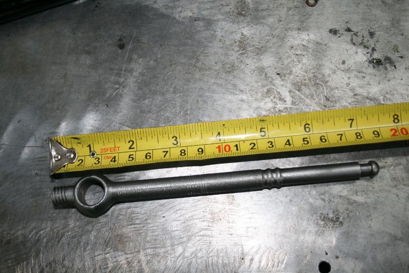
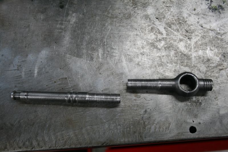
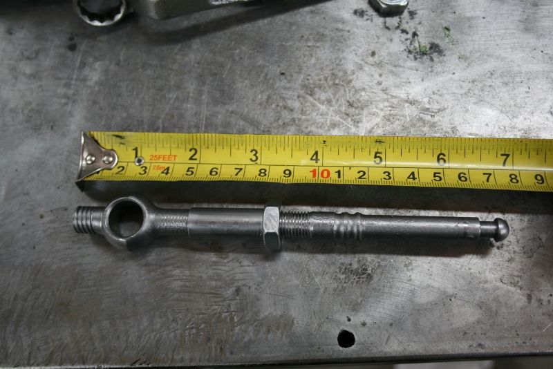
Got the brake push rod thing figured out, turns out it was operator error. After chasing my tail the other day, I finally took the master cylinder off the firewall and had a look to see what was happening, I figured I had to be doing something wrong. Turns out it takes a good amount of effort to get the tip of the rod to seat in the back of the piston with the retainer, it's kinda tough to get it to pop in all the way when you're under the dash. I stuck the M.C. in the vise, put a little lube on the tip and worked it in. I've done a few of these now but I failed to remember this little tidbit for some reason. Oh well. It's in and stays in. Cost me a few bucks for an adjustable push rod but its a cool piece and I can adjust the pedal height now if needed.

Also got the column issues figured out. After taking the whole thing out again, I learned there was no hole for the retaining pin in the coupler body. I thought it may have been hiding under the ridge where the cover gets crimped to (which was bent over) but there was no hole. I pried it back to see but again, no hole. :dontknow:

The problem seems to be with the back of the key release collar - it was rubbing/binding on the bottom of the cluster. Because of this, the lower column cover could not be installed correctly. I pried the column bracket forward and back to see I could adjust it but there was no spot where everything would fit and not pull the shoes out of the coupler.

The decision was made to ditch the lower cover for now and not have it pull the shoes out of the coupler. The lower cover I have is broken anyway. Might have to modify one to get it to fit without interfering with the key release collar. Doesn't seem right to me but it's working OK and the shaft is not collapsed. Maybe there is a specific collar for a Tuff Wheel/floor shift/manual column? Dunno.

Finished up some more wiring in the engine bay, mostly in regards to the neutral safety switch and a ground strap from the driver's side head to the frame. I am 95% done with all the wiring at this point, just a few odds and ends to take care of. I will be stoked to stop measuring/crimping/soldering/heat shrinking/wire-tying.

Finished up the Line Lock too and the remainder of the brake lines. The L.L. pipe fittings were coated with Teflon paste and installed for good. The rear lines were cinched down, as well as the rear flex line and axle vent fitting. I'm happy with how it came out.

The rear end is finished and the rear wheels are back on the ground which means the Cal Tracs are installed. Since the car has offset springs, there are some clearance issues with the front spring hangers that needed to be dealt with. The inside Calvert triangulated pivot bracket needs to be trimmed under the spring eye hole to allow full forward swing motion without hitting and thus binding on the inside bottom of the offset hanger. So much for the nice powder coated finish! I am using Cass's offset hanger kit which is WAY nicer and lighter than the old Mopar Performance set but the pivot bracket still needs to be trimmed. See pics below.

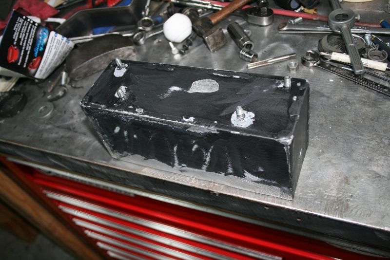
I finally got to install my fancy Summit aluminum trans pan. This thing is beefy. Got a lovely, modern Mopar steel'n'silicone gasket from a later 42 to prevent leaks. The trans fluid was red and clear. There were traces of shiny stuff in the pan but I'm not concerned, the trans was working good.

While the old pan was off, I learned I have a Cheetah valve body, #17680. This is their 'race' FMVB which does not have the low band apply. The theory with this valve body is that it makes the 1-2 shift quicker. There are a few caveats with this part though. At the track, you must do your burnout in 2nd, shift into third and let off slowly when the tires bite. The other issue is driving on the street. Since there is no engine braking in first, it can be a little tricky. You have to be on your toes and need to be ready to upshift or coast if you let off. You can't get off and on the throttle in low quickly or you will kill the sprag. 2nd and third are 'OK' since those gears have engine braking but I try not to hammer it if I let off. I don't spend a whole lot of time in low so I'm used to it but you definitely need to be aware of it in traffic.

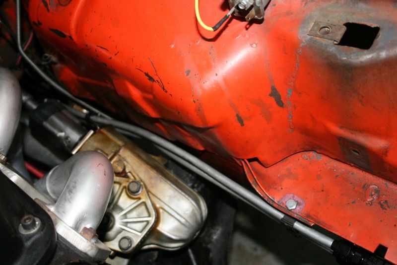
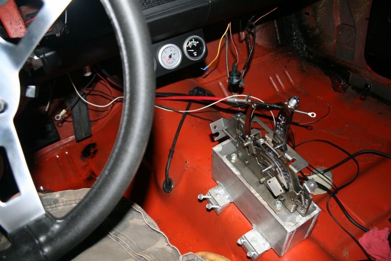
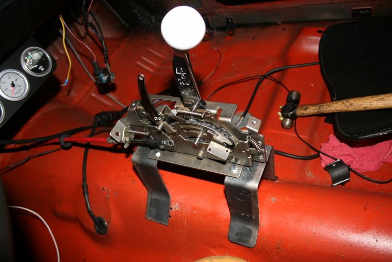
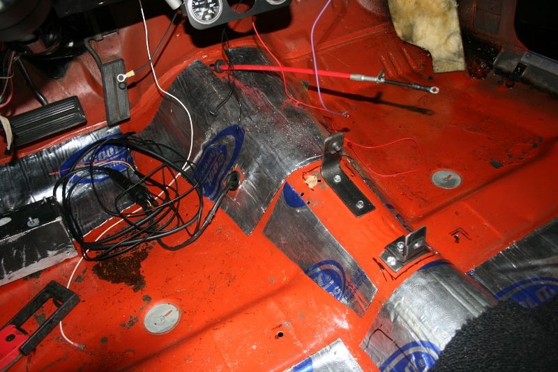
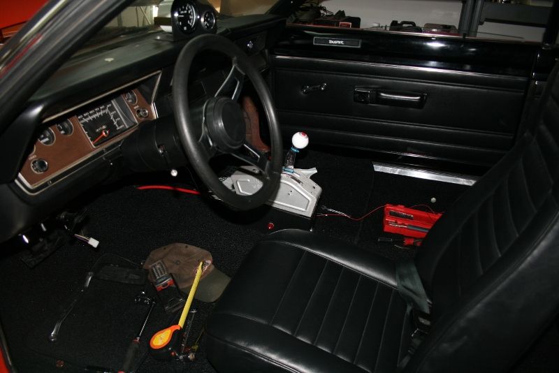
Unfortunately though, I've encountered another road block with the shifter cable. When it was first installed, there was a bench seat in the car and it was mounted almost a foot forward of where it is now. I moved it back to a more comfortable position with the buckets in it which effectively altered the length of the cable. Initially it was looped around the starter and secured to the trans-to-engine brace. But now since it's further back, there is not enough length to reach around the starter and it lays right on the header tube.

The original hole for the cable to go through the floor is now too far forward so I will have to drill another one closer to the shifter. I've been looking at it trying to figure out how to route it, I've seen where guys run it towards the passenger side first then loop around the bell and back to the selector lever. Might have to get a different length cable to make it work but we'll see how it goes. I think I can make it work somehow.

And to whoever has been reading through this - thanks for sticking with me! I know I can get a bit wordy with the descriptions, hope I'm not boring everyone to death with all the little details. I always think it might be helpful to someone who runs into the same situation. I also do it for myself to have a document of what I did.

OK, on to some pics. I didn't get images of all the issues I described this time, just the ground wire I made and the Cal Trac bracket trimming.

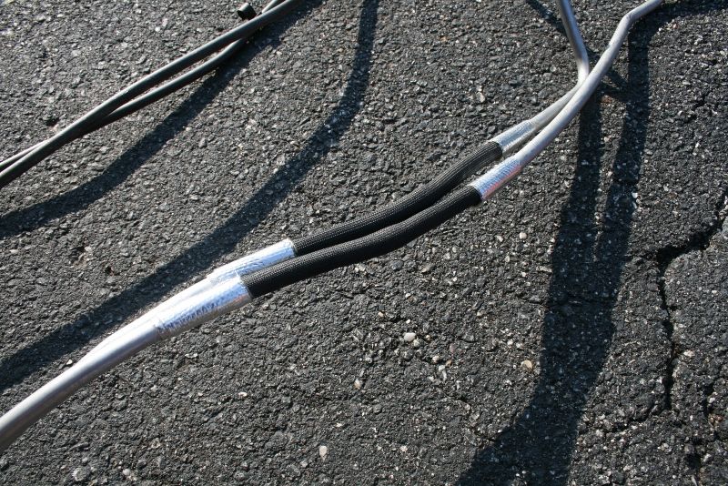
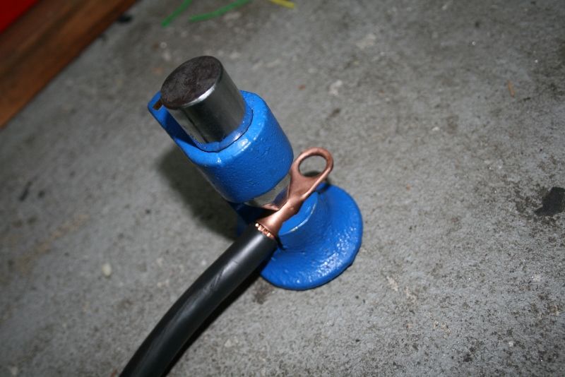
The ground strap is 00 wire. I use my Grainger hammer crimp tool for big cable ends.
IMG_9959800x534_zps96304617.jpg


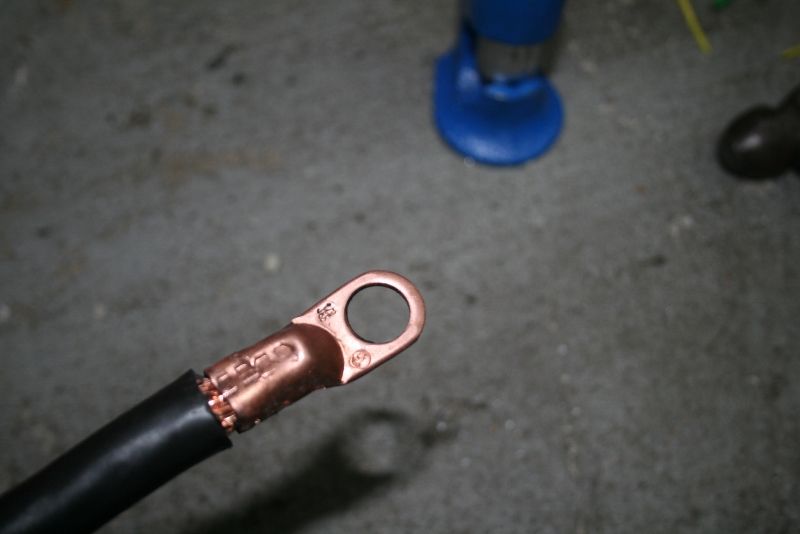
Here's the crimp job. It's solid.
IMG_9960800x534_zpsc20acd31.jpg


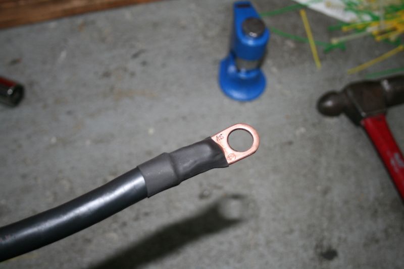
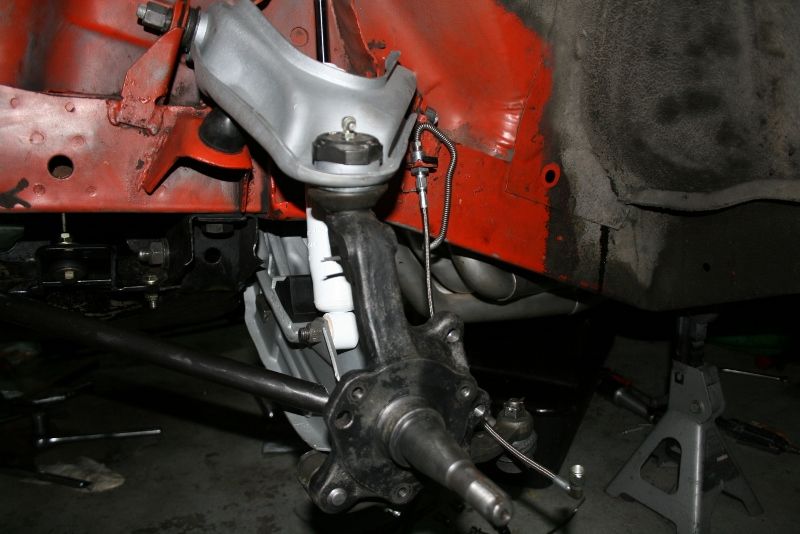
Final step is to heat shrink. I'm just realizing now that I forgot to solder it. It attaches from the left cylinder head to the bottom of the frame between the K member. I made sure to leave enough slack for movement.
IMG_9963800x534_zps5609f777.jpg


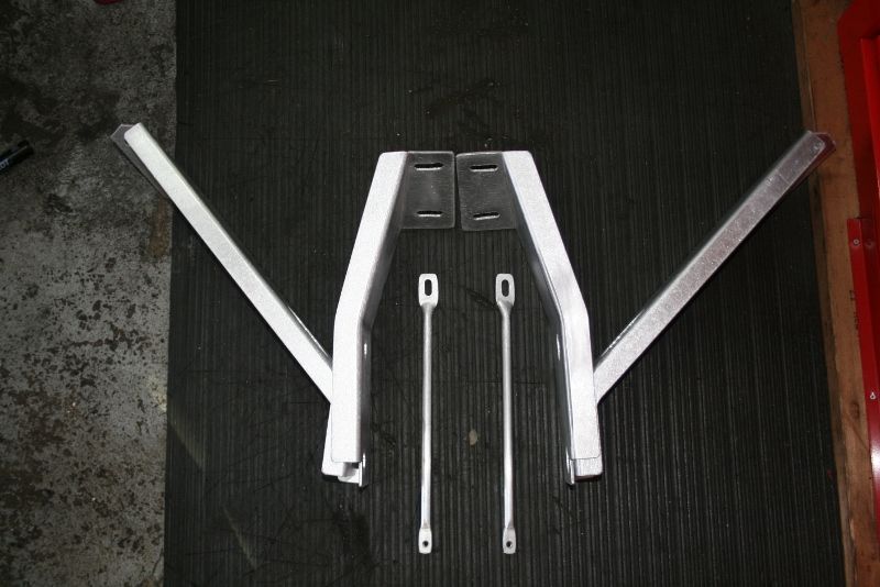
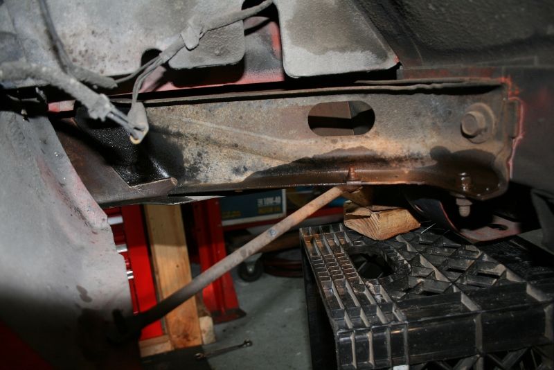
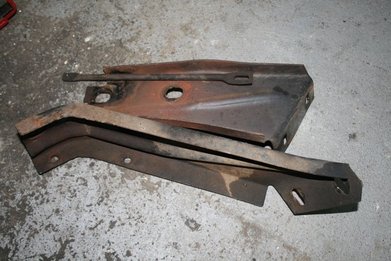
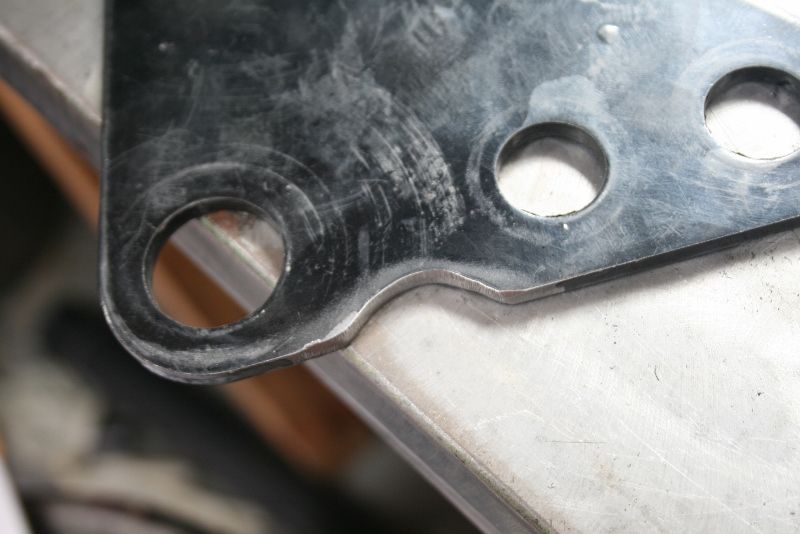
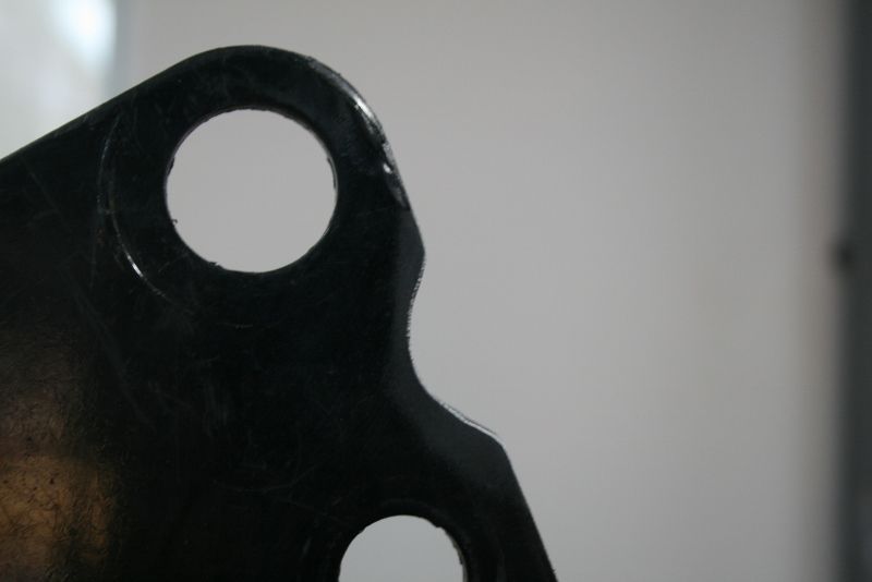
OK, here are pics of how the Calvert bracket needs to be trimmed. The half-moon relief is where it hits the inside/bottom of the offset spring hanger. If you can picture where this part is installed, you can probably see how it could bind.
IMG_9955800x534_zps3d78cbaa.jpg


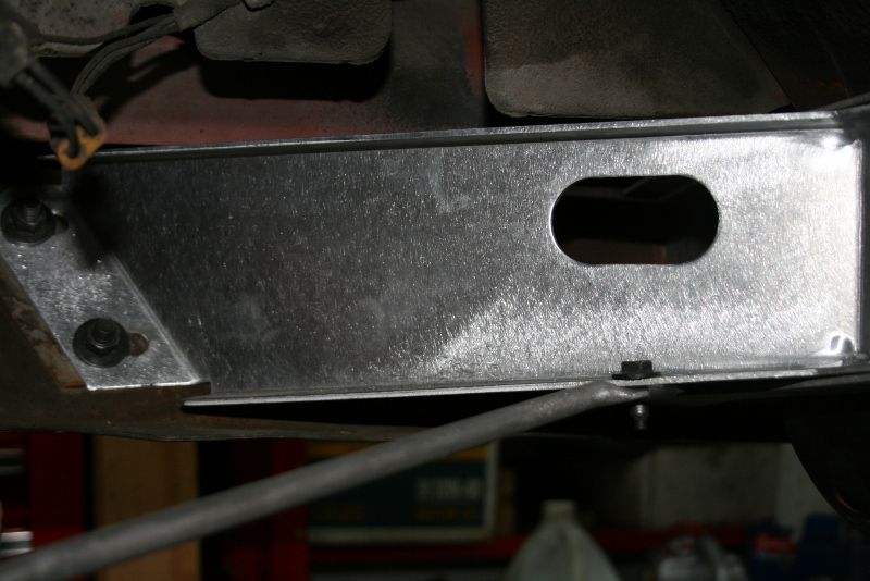
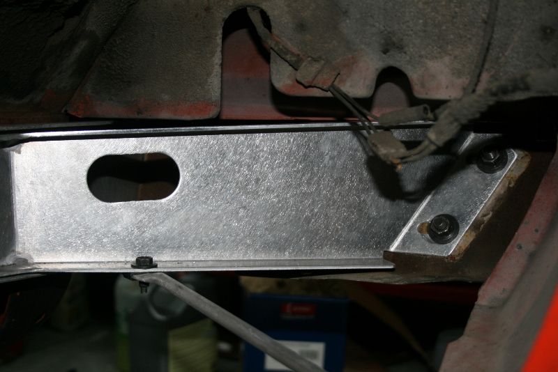
Here's another pic from a different angle.
IMG_9956800x534_zpscbfb34af.jpg


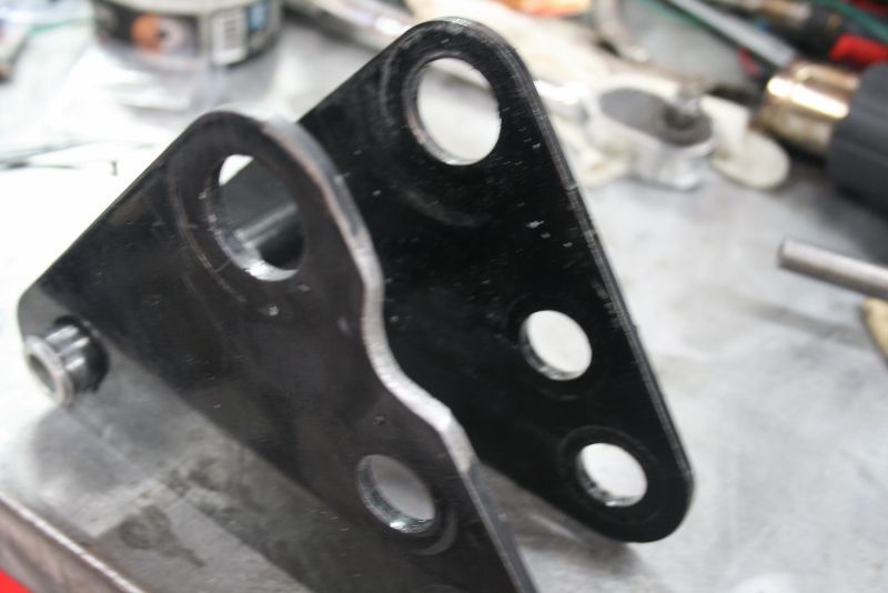
Here's the triangle pivot bracket. You can see only the inside needs to be trimmed, there's plenty of room on the outside for full swing motion.
IMG_9957800x534_zps694da2e8.jpg


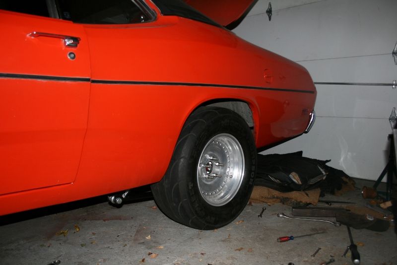
And here's the rear wheels back on the car.
IMG_9964800x534_zpsa758ade9.jpg


More to come.
 
The front end is rebuilt. Just have to lube the torsion bars and its on to the brakes. Hope to have the car back on all four wheels soon, could be the next couple days or so.

Light at the end of the tunnel is getting brighter.

Couple pics of the front end components. Note beefy strut rods and braided brake hose from Mancini, Calvert front shocks and KH disk brake spindles awaiting rotors.
IMG_9985800x534_zpseb20c26c.jpg


Right side. Can't really see 'em but I have aluminum tie rod adjuster sleeves, also from Mancini. The right side UCA was a ***** to get in BTW.
IMG_9983800x534_zps83785973.jpg


Didn't bend the cotter pins yet, gonna re-check everything when it's on the ground. Zerk fittings are in for grease, hope to be done with this by the weekend. Nice to work with clean new parts!

More to come.
 
Impressive. You upgrade the minor things,that make a huge difference. I love the functionality idea.
 
-
Back
Top