too much voltage after adding headlight relays

-

hobbsza

Active Member
Joined
Dec 2, 2015
Messages
44
Reaction score
2
Location
oceanside ca
I'm having an issue with my voltage being around 16 volts after I added the headlight relays. I used 12 gauge wiring and followed a diagram I found on the forum. everything was working fine until after I did the...... "upgrade" lol the car is a 1974 Plymouth duster 318. could my issue be a bad ground? or if anyone can find a post where someone else ran into this can you please put it in my direction thanks everyone
 
Bad ground on the voltage regulator will do that. Or somehow the 12v feed to the regulator is low and it is overreacting.... Or the green field lead from the alternator to the regulator is grounded.
 
thanks for the quick response. i checked the ground for vr and it is good. so could i just jump from the batt straight to the vr? and which of the 2 prongs would i go to? sorry for the ridiculous questions i would normally refer to my grandfather but cancer got him a few years ago so now you guys get to hear them lol
 
Sorry about your grandfather..... musta been good to have him as your 'go to' expert.

If you are talking about the 12 v feed to the VR, no, that has to be switched by the ignition. It is the blue wire feed to the VR. Do you have a voltmeter? If not, time to go get a cheap one. You'll be using it on these old Mopars.

But it sounds like you do have one. See if you can probe the blue wire into the regulator, and see what voltage you have there compared to the battery + while running at fast idle. Keep your - lead to the meter at the battery - for all of these measurements.

And is the 12v that is switched by the relays and sent to the headlights coming directly from the battery or where? Can you link the diagram that you used?
 
It's coming straight from the starter relay I'll see if I can find the diagram again. The headlights (hid conversion kit) all work perfectly when the car is off but when it's on they flicker from thee voltage being too high.
 
That sounds like a good place to take it from. Is the rest of the wiring stock? So DO you have a voltmeter?
 
That sounds like a good place to take it from. Is the rest of the wiring stock? So DO you have a voltmeter?
I have a volt meter and I replaced all the old wiring with new 12 gauge. And grounded the headlight relays back to the starter relay mount, and the headlight ground goes back to where the battery ground connects to the radiator support
 
I'm only getting 11.4v when I check the blue wire with the car at a fast idle and the battery itself has 15.4v at fast idle so where are the possible places it could be loosing that voltage from? I'm going to trace the blue wire and see if there are any issues with it. The previous owner did some really sketchy wiring on the aftermarket instrument cluster could the issue be there? It's next on my issues to fix and probably make worse lol
 
Last edited:
Check the bulkhead connector, and steering column connector. You have high resistance in the switched ignition circuit (blue). You can also add a relay to the VR. Use the blue ignition feed to activate the relay. battery to relay 30, blue from alt to 87. adding the relay allows the VR to sense battery voltage and eliminates the voltage drop in the switched ignition circuit.
 
I'm only getting 11.4v when I check the blue wire with the car at a fast idle and the battery itself has 15.4v at fast idle so where are the possible places it could be loosing that voltage from? I'm going to trace the blue wire and see if there are any issues with it. The previous owner did some really sketchy wiring on the aftermarket instrument cluster could the issue be there? It's next on my issues to fix and probably make worse lol
You are absolutely on the right track. If the regulator sees a low voltage, it commands the alternator to put out more to try to get about 13-14 volts on that blue wire. As said: bulkhead connectors in and out of the dash area, steering column connectors, and ignition switch are all in the path. And there are sometimes underhood connectors in that blue wire path. If there are crappily added connections under the dash, that can do it too.
 
Checked the instrument cluster and the blue wire with the white stripe was running the dash lights so I'm going to disconnect that and switch it to the orange wire where it's supposed to be. Do I need to have the blue wire connected to anything or can I just cut the previous owners mess out and heat shrink/tape the wire off so it can't make contact with anything?
 
Mmmmm, aren't you tracing the dark blue wire from the voltage regulator (and one field wire to the back of the alternator and the stock ignition if you have that)? That goes through connection N on the firewall and then to the ignition switch via a connector on the steering column.
 
Everything looked ok so I was looking at the diagram for the instrument cluster plug and it said the blue and white wire pin1 is the 12v ignition so I checked it. Am I getting off track?
 
Well I traced it back to the ballast resistor. If I unplug the drivers side plug I get the same voltage at the blue wire as I do at the battery. So I'm off to the parts store for a new ballast resistor
 
Whoa.....! It sounds like the ballast is drawing normal current. DON'T toss your ballast in case it is an original one! The parts stores will give you a wrong replacement most of the time.

The voltage regulator and the ballast draw current from the same source: The ignition switch, through the blue wire. You probably have a high resistance connection between the ignition switch and the VR and ballast. So back up.

The blue wire does not come from the instrument cluster connecotr. It comes from the ignition switch through a connector on/under the steering column. It then passes through the bulkhead
 
Whoa.....! It sounds like the ballast is drawing normal current. DON'T toss your ballast in case it is an original one! The parts stores will give you a wrong replacement most of the time.

The voltage regulator and the ballast draw current from the same source: The ignition switch, through the blue wire. You probably have a high resistance connection between the ignition switch and the VR and ballast or into the ignition switch. So back up.

The blue wire does not come from the instrument cluster connector. It comes from the ignition switch through a connector on/under the steering column. It then passes through the bulkhead connector to the engine bay.

12 v gets to the ignition switch from the large lug on the starter relay through a fusible link to another firewall connection that leads to a welded splice in the harness. That feeds a red wire to the ignition switch in the same connector under the steering column through which the blue wire to the VR and ballast runs.

The voltage drop can be going into the ignition switch from the big lug on the starter relay, inside the ignition switch, or from the switch to the VR, so you have to probe it all along those paths.

BTW, when you have the high voltage while running, what voltage is on the large lug of the starter relay, where you connected your new light wiring?
 
After I replaced the resistor my battery and solenoid lug are at 15.2 and the blue wire is now at 12.4 at a fast idle. I retained my old resistor until I find the actual problem I'm going to continue probing it just don't understand how it was all fine until I added the relay.
 
I'll make a guess... they gave you the wrong ballast and its resistance is higher (too high), thus it draws less current so the total current draw on the blue wire lower. This would make the voltage drop wherever it is occuring less and so you are seeing more voltage to the VR and it is trying less hard to boost the voltage to compensate. So, yes, hold on to the old ballast.

Check the voltage while running in the following order; the voltage will would normally very slightly at each point but it will drop at one of those points a lot and you will know it is back upstream from there. Keep the - lead of the voltmeter to the same ground point at all these readings.
1. Large lug at the starter relay
2. After the fusible link to the bulkhead connector (connection J)
3. At the red wire in the harness connection to the ignition switch under the steering column
4. At the dark blue wire in the harness connection to the ignition switch under the steering column
5. At Pin N of the same bulkhead connector as in 2 on the dark blue wire
6. At any point you can access in the dark blue wiring to the VR

Why? The connections in these cars get old and corroded and wires get hard and can crack. You probably disturbed something that was on the edge of being bad. Don't worry at this point; troubleshoot as above. When you find the problem, the 'why' may become obvious.
 
I had to do the tests with the car off due to neighbors complaining about my car they must not be American if they don't enjoy the sound lol but the ignition was set in the run position and I believe I have narrowed it down to somewhere behind the dash. I had 12.3 on the red wire and 11.4 on the blue wire both readings taken from inside the car. I ran out of time to continue poking around. I'll pick it back up tomorrow and hopefully find the issue.
 
You are on the right track but you have to understand how "this works."

Start by reading the Mad article, which points out the problems in the old wiring in these girls, and look over the simplified diagram on that page:

Catalog

amp-ga18.jpg


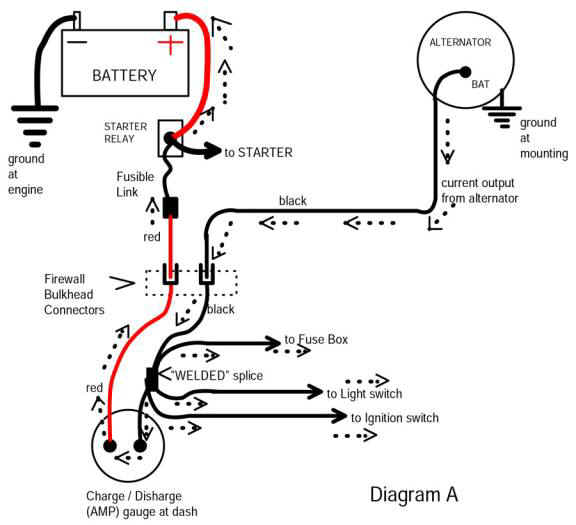
Follow the "path" from the battery. You are getting a voltage drop somewhere between the battery and the VR IGN terminal

From the battery, through to the junction stud on the start relay, through the fuse link, through the BULKHEAD CONNECTOR (RED) to the AMMETER, through it, out on the BLACK ammeter wire, and to the WELDED SPLICE. That branches off and feeds power to

the HEADLIGHTS only power to the light switch

the HOT BUSS in the fuse panel

the FEED TO the IGNITION SWITCH, so to the IGNITION SWITCH CONNECTOR, THROUGH THE SWITCH, OUT THE SWITCH CONNECTOR (on the blue "ign run" wire.......back through the BULKHEAD CONNECTOR........to the ignition, the VR ign terminal, and other underhood loads.

EACH point in CAPS is a potential problem area. It is rare, but there has been a few cases whereby the welded splice itself has loosened up.

In no real order, your top suspects are the bulkhead connector, the ignition switch connector, the ammeter and it's connections, the ignition switch, and as mentioned "rare" the welded splice.

If you don't have one, waltz over to MyMopar and download yourself a free service manual. Some of those there, came from the guys here at FABO

MyMopar - Mopar Forums & Information - MyMopar Tools/Reference

VOLTAGE DROP in the ignition feed to the VR is probably the number one reason for over charging/ over voltage.

Other causes are:

Voltage drop in the ground to the VR, IE between VR and battery NEG

a bad VR

a bad battery.
 
Last edited:
I had to do the tests with the car off due to neighbors complaining about my car they must not be American if they don't enjoy the sound lol but the ignition was set in the run position and I believe I have narrowed it down to somewhere behind the dash. I had 12.3 on the red wire and 11.4 on the blue wire both readings taken from inside the car. I ran out of time to continue poking around. I'll pick it back up tomorrow and hopefully find the issue.
Good for you..... that drop is in and out of the ignition switch. Those do go bad sometimes.....keep measuring as it can be in multiple places. Take readings and record them at all the spots ID'd so you can see what is going on. It would be good to post them here.
 
haven't posted in a while and I replaced the ignition switch and I thought all was well now the issue is when I start the car it is at 15.2v but it doesn't climb with rpm or anything like that, after the car gets warm and runs for about 10min the volts go down to about 14.6 and stay there still no climbing in voltage with rpm. is this a sign of something going bad or am I still missing something?
 
There is temperature compensation in the regulator. It attempts to follow battery charge profile with temperature. When cold battery voltage charge voltage is higher, when hot, battery charge voltage is lower. The regulator is remote to
battery, so temperature approximate, it does not include battery heating from, charge or discharge. More exact systems have temperature probe on battery.

The battery voltage is still higher than normal, so more drop somewhere. 13.8V is more typical. Voltage vs RPM should be stable, except for older regulators, that fail to reach desired voltage at high load while at idle. The blue IGN wire at regulator, and battery voltage should be within a couple tenths of a volt, battery voltage being higher.
 
Last edited:
kit Carlson where exactly are you at in middle TN? I'm originally from McMinnville I'm just stationed at Camp Pendleton right now I actually get out of the usmc on September 1st and I'm planning to drive rt66 back. thanks for the response ill redo all of my checks and see what I come up with.
 
well it looks like another ignition switch. is there a brand that doesn't have this garbage plastic on it this will be the second new one ive put in :mad::BangHead:. the first one that I bought the plastic back plate completely just fell off so I'm sure this one is going to be close to it
 
-
Back
Top