This one is not finished yet, I am still editing it... You are welcome to look at what I have so far, but keep in mind it is far from finished... Please check back later when it is finished... I will remove this text when it is done...
Now we are going to install the alternator and pulleys for non-A/C applications with stock pulleys... In the last chapter we painted the engine...
This is the next step to continue after Sections 1 - 20... If you missed one of them, you can find it here...
How to Rebuild a Small Block Part 1: Block Prep
How to Rebuild a Small Block Part 2: Cam Bearing Install
How to Rebuild a Small Block Part 3: Install Water Jacket and Oil Galley Plugs
How to Rebuild a Small Block Part 4: Pre Flight Inspection After Machine Shop Before Assembly
How to Rebuild a Small Block Part 5: Crankshaft Install
How to Rebuild a Small Block Part 6: Installing Rings on Pistons
How to Rebuild a Small Block Part 7: Install Pistons in Block
How to Rebuild a Small Block Part 7a (Optional): CC the Engine Cylinder to Find Compression
How to Rebuild a Small Block Part 8: Install the Camshaft
How to Rebuild a Small Block Part 9: Install Camshaft Thrust Plate
How to Rebuild a Small Block Part 9A (Optional): Timing Chain Options
How to Rebuild a Small Block Part 10: Install Timing Chain
How to Rebuild a Small Block Part 11: Check Piston-to-Valve Clearance
How to Rebuild a Small Block Part 12: Installing the Heads
https://www.forabodiesonly.com/mopar/ams/how-to-rebuild-a-small-block-part-13-installing-the-valvetrain.442/
How to Rebuild a Small Block Part 14: Preparing the Timing Chain Cover
How to Rebuild a Small Block Part 15: Installing the Timing Chain Cover and Water Pump
How to Rebuild a Small Block Part 16: Installing the Distributor Gear, Oil Pump, and Windage Tray
How to Rebuild a Small Block Part 17: Installing the Intake Manifold
How to Rebuild a Small Block Part 18: Installing the Oil Pan
How to Rebuild a Small Block Part 19: Installing the Valve Covers and Oil Filter Adapter
How to Rebuild a Small Block Part 20: Painting the Engine
*************************************************************************
Hello everyone, it's Krazykuda here to show you how to rebuild a small block... This article is to help any newbies through rebuilding a small block Mopar LA engine, but may have a few tips that some of you seasoned builders may find useful... If you haven't ever built an engine, I will show you what you need to know to do it yourself...
The goal of this series is to show what you can do at home in your own garage... Go at your own pace and ability and then take it to someone knowledgeable for what you are not capable of doing yourself or don't have the proper equipment/tools for...
Keep checking back in from time to time as this is a work in progress and I plan to keep updating it as I build more engines and can show you more variations...
I am going to break this into sections that you can follow along with and make sense to do in 'stages' when you build... Plus you can then jump to the section that you are working on to help keep from sorting through one very long thread to find what part that you are working on when you are doing it....
*************************************************************************
*** Important Note *** Sometimes things may not go right and you will run into a snag/road block... Do not get in a hurry to finish and take short cuts that may compromise your build...
Step back, take a break, and think about it for a while... Or seek help from other experienced people or professionals to overcome the problem... Do it right and don't take any unnecessary chances that may compromise the integrity of your build...
If you don't fix the problem correctly, it may come back to haunt you and cost even more time and money than if you took the time to think about it and research it to fix the problem correctly...
This has been a public service announcement from krazykuda....
*************************************************************************
This chapter I'll show you how to set up the pulleys for the two different water pump configurations for non A/C applications so the belts line-up properly using stock pulleys for your engine; early style (1964 - 1969) vs later style (1970 and Later)...
*************************************************************************
There are two different styles of water pumps that came on the small block Mopar engine from the factory. The early style was used from 1964 - 1969 and had the cast iron water pump... The later style was used from 1970 and later and used the aluminum water pump...
Here are the two different style alternator mounting brackets side by side so you can see the difference... The 70 and later style is in the Mancini Racing package and I set the early style on the outside of the package next to the individual brackets so you can see the difference... The early style are painted silver...
The later style alternator mounting bracket is the one in the package and is a simple triangle with 3 holes... This bracket attaches to the engine using the two long bolts that pass through the water pump and timing chain and thread into the engine block...
The early style alternator mounting bracket is the one on top and is triangle shaped with 4 holes... The hole in the middle uses a short 3/8" x 18 threaded bolt to attach it to a threaded boss on the cast iron water pump...
The early style alternator adjusting bracket is the silver one on the outside of the package and you can tell this one because it has the bend in the middle... The later style long bracket is straight without any bends...
The bottom alternator adjusting bracket mounts over the triangular bracket on the bottom hole and has a long curved slot to adjust the tension on the alternator belt...

Here's a top view with the long adjusting brackets with the curved slot for adjustment...

*************************************************************************
70 and later alternator mounting brackets...
This is the Mancini Racing 70 and later alternator bracket package... It comes with the triangular mounting bracket, the long slotted adjustment bracket, and the long alternator mounting bolt and spacers to mount the alternator...


Here's the link for the Mancini Racing 70 and later alternator bracket mounting kit...
Mancini Racing - Alternator Mounting Kit
They also sell just the long alternator mounting bolt and spacers...
Mancini Racing Alternator Mounting Bolt Kit
Here's the Bouchillon Performance 70 and later alternator bracket mounting kit that comes with everything to mount the alternator... It includes both bolts for brackets, the long mounting bolt and spacers for the alternator and the short adjusting bolt for the alternator that goes through the adjusting slot... The brackets and long alternator bolt and spacers that come with it are not in this kit because we already used them before taking the pictures... This is the more complete kit...


Here is the link to the alternator bracket mounting kit from Bouchillon Performance...
5251 alternator brackets - Bouchillon Performance Engineering
Bouchillon also sells all of the bolts in a package in case you have the brackets and need the bolts...
https://www.bouchillonperformance.com/inc/sdetail/831/841
*************************************************************************
Early style alternator mounting brackets...
Here is the set of early style alternator mounting and adjusting brackets shown as they go on the engine... The long slotted bracket always goes on top of the triangular bracket like this...

Top view...


Mancini Racing also sells a early style alternator bracket kit...
Mancini Racing - Alternator Mounting Kit
They also sell the long alternator mounting bolt with the 3 spacers if you already have the brackets and only need the bolts and spacers...
Mancini Racing Alternator Mounting Bolt Kit
Bouchillon does not sell the early style alternator brackets or bolts...
*************************************************************************
70 and later style alternator bracket mounting...
You need to use a single groove pulley on the alternator when using these brackets for this vintage engine for the pulley to line up correctly with the crankshaft pulley... This is if you set up the engine for no A/C or removing the A/C on a factory A/C car... The cars that came with A/C used double alternator pulleys with two alternator belts for the A/C... If you are using the factory A/C system, you need the proper A/C setup that came from the factory... I don't have any 70 and later cars with factory A/C to show...
In addition to changing to the aluminum water pump in 1970, they also started using what they call the "square back" alternator... It got it's name because the back of the alternator has a rectangular shape to it "squared"... They also changed the from the old solid state to the electronic voltage regulator...
From the front it looks similar to the older alternator, you can tell by looking at the back...

Here is the back showing the rectangular pattern in the casting...

Here I circled it in red...

Here is how the 70 and later alternator brackets mount to the engine... The ling bracket goes on top of the bottom hole for the triangular bracket and it mounts on the two long bolts that go through the passenger side water pump and timing chain cover... A short 5/16 x 18 bolt goes through curved slot in the long bracket and threads into the bottom of the alternator... This is used to tighten the belt...

The ear on the alternator goes in front of the top hole in the alternator bracket... Then the long spacer goes behind the bracket and in front of the rear mounting ear of the alternator... It is best to keep the two water pump bolts loose while installing the alternator and spacers so you can wiggle them together... If the water pump bolts are torqued, it will be difficult to get the long bolt in with all of the spacers, especially the shorter one on the back... Once you get the top bolt and spacers in, then you can retighten the two water pump bolts...

Here is a top view showing how the brackets and spacers are supposed to go together...

Here it is in a car from the back with all the wires connected...

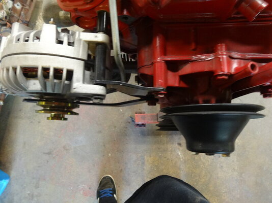
Here's a side view showing that the alternator pulley is lined cup correctly with the crank pulley... Dead on...

*************************************************************************
Early style alternator bracket mounting...
The two early style alternator brackets to together like this... The long slotted one always goes on top of the bottom triangle bracket mounting bolt...


Here is the cast iron water pump.... The triangle bracket bolts to the three holes on the left side of the picture here...

The Triangle bracket uses these two long bolts to mount the two holes on the right side of the bracket...

However the boss for the top hole is lower than the bottom bolt, so there is a small spacer that goes between the top bracket hole and the water pump to fill the gap...

Here is a closer view showing that the top boss is shorter than the two others..


The boss on the far left side of the water pump is threaded and a short 3/8" x 16 bolt is used to attach the alternator bracket to the water pump through the center hole in the bracket...


The short 3/8" x 16 bolt goes through this hole and threads into the threaded hole in the water pump...

Here are the brackets on an engine shown how they fit together...

Here's a front view...

This side shot shows why you shouldn't run a double pulley on the alternator... The belt won't line up correctly and will bias the load to one edge of the belt... It will work, but in the long term you will wear out your belt faster and have to change it more often... The single groove pulley lines up correctly and will spread the load and wear to both sides of the belt for longer life...

Here is the back of the early style alternator, they call this the "rounback" alternator... It doesn't have the rectangular ribs in the back like the 70 and later style alternators...

*************************************************************************
Water pump/cooling fan pulley...
The water pump pulley also spins the cooling fan... It has two purposes, one to spin the water pump and circulate antifreeze through the engine to take the heat away from the cylinders because there is an explosion going on in there that generates alot of heat... Too much heat can damage the cast iron of the block, so you have to have coolant/antifreeze flowing around the cylinder block and heads to take the heat away... The heated antifreeze then flows out of the water pump through into the radiator through the lower water pump outlet and radiator hose...
The coolant then passes through small tubes in the radiator that have fins on them to help get rid of the heat into the air that passes through the radiator... It is important to have good airflow through the radiator fins so it can transfer heat to the air...
The coolant then exits the radiator through the upper hose into the thermostat and circulates around the engine...
The cooling fan is used to help pull air through the radiator fins to take away the extra heat so it can recirculate back into the engine and make another loop... Having a fan shroud on the back of the radiator helps direct the air into the fan so it can pull air more efficiently... The shroud acts like a nozzle or funnel to help the fan pull air through the radiator fins...
What you need to take away from my long explanation is the fan pulley does two jobs, but has one purpose - to keep the engine cool so it doesn't overheat...
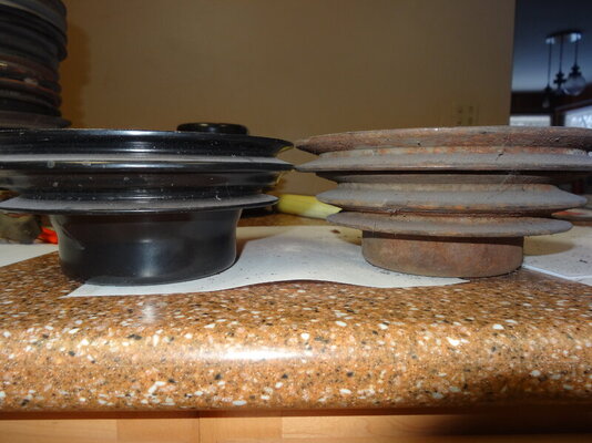
What's the difference between the early style 64 - 69 type and the 70 and later water pump/cooling fan pulley???
I'm glad you asked...
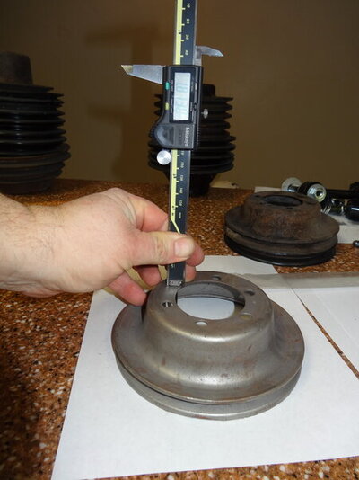
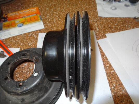
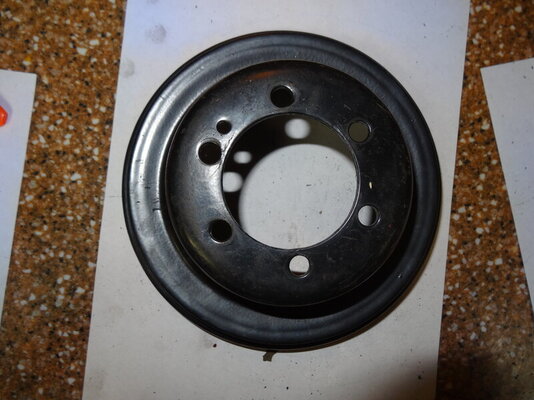
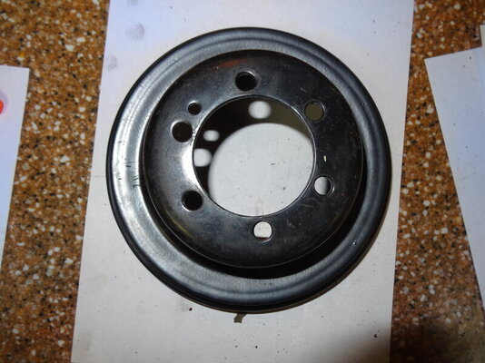
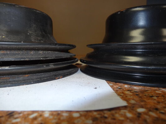
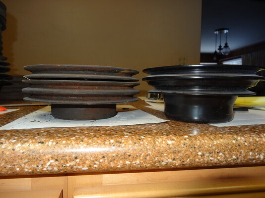
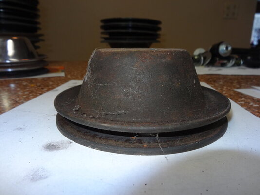
The early style has a bell shape to it and the sides are perpendicular to each other, where the 70 and later has angled sides...
Here is the early style what I call the bell shaped pulley...


Here is the 70 and later pulley with the angled sides...

*************************************************************************
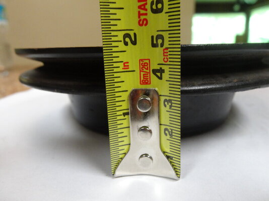
Early style water pump pulleys...
Here's a no power steering 68 340 Barracuda with a single groove crankshaft pulley...


The depth looks like 1 13/16" from the front of the vibration damper...

The diameter is 6 3/8"


*************************************************************************
*************************************************************************
Power steering brackets for a 69 340 Dart...
Here are how the brackets go on a 69 power steering pump to mount it...


*************************************************************************
Here are the assembled alternator brackets, water pump pulley, and power steering mounting on a 69 Dart with a 340 and power steering...


You can read the part number on this gates belt, it is 7614GVBZ... The first number 7 is the series of the belt which determines the width of the belt, the next 3 numbers give the length in inches, so this belt is 61.4" length... Gates are my preferred belts as they are good quality... Goodyear belts are also very good...


*************************************************************************
70 and later pulley links...
Here are the links for the Mancini Racing 70 and later water pump pulleys...
Painted...
Water Pump Pulley w/o AC
Chrome...
Chrome Water Pump Pulley w/o A/C
Here are the 70 and later crankshaft pulleys...
Single groove..
Painted...
Crankshaft Pulley w/o Power Steering & AC
Chrome...
Chrome Crank Pulley w/o Power Steering & AC
Double groove...
Painted...
Crankshaft Pulley with Power Steering w/o AC
Chrome...
https://www.manciniracing.com/maabchcrwipo.html
Here's the links for the Bouchillon Performance 70 and later water pump pulley...
Painted...
BPE Water Pump Pulley - Bouchillon Performance Engineering
Chrome...
BPE Chrome Water Pump Pulley - Bouchillon Performance Engineering
Crankshaft pulleys 70 and later...
Here's the link for the Bouchillon Performance crankshaft pulley page...
Products: Crankshaft Pulleys - Bouchillon Performance Engineering
Here's their links for the single groove crankshaft pulley...
Painted...
BPE Single-Groove Crankshaft Pulley - Bouchillon Performance Engineering
Chrome...
BPE Single-Groove Crankshaft Pulley (Chrome) - Bouchillon Performance Engineering
Here's their links for the double groove crankshaft pulley...
Painted...
BPE Double-Groove Crankshaft Pulley - Bouchillon Performance Engineering
Chrome...
BPE Double-Groove Crankshaft Pulley (Chrome) - Bouchillon Performance Engineering
*************************************************************************
70 and later pulleys...
Now the alternator is mounted, we need to get the rest of the pulleys together...
This example shows my son's 71 valiant with a 91 360 and power steering... We need to use a double groove crank pulley...
It shows at 7 1/4" diameter for the outer groove...


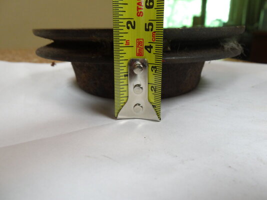
When you place the small part on a table, the top edge is 3 1/4" tall...

The water pump pulley measures a little over 6 3/4" to 6 13/16" diameter...

When you put the small end on a table, the top edge is 2 3/4" tall...

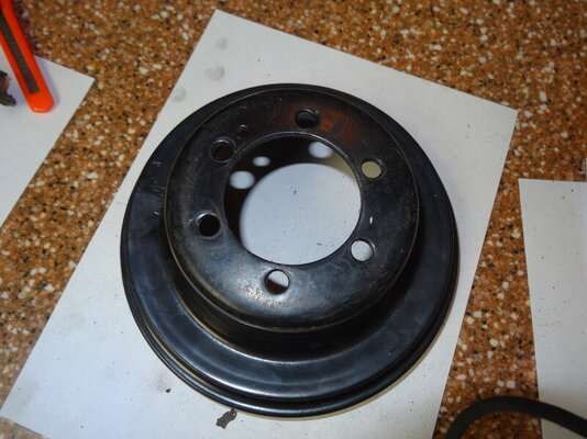
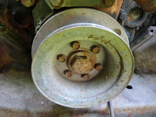
One point to make with crank pulleys... Some vibration dampers had a symmetrical bolt pattern and others had a non-symmetrical bolt pattern... I don't know what years for each or why Chrysler did this... But you can interchange the pulleys from different bolt patterns with a simple trick so you can use all 6 bolts in pulley to mount it... The pulleys don't affect the balance of the engine so it's ok to swap them... As long as they have the proper groove spacing and diameter you should be ok...
If you have a mis-matched pulley for the bolt pattern on your vibration damper, don't worry... Just take the pulley and match it up to the vibraton damper... Keep rotating the pulley to different blot holes and you will find that you can get 5 out of 6 holes to line up and one will be just a little off... Take a paint pen or marker and mark that bolt toward the side where the bolt hole overlaps the threaded hole on the damper... Now take a burr and grind that hole to make is oval shaped so you will be able to get the bolt through it...
Here is one that I marked... I don't have an after picture, but it worked... If you worry about that hole being a little bigger, just put a washer on it so the bolt will hold properly...


Here's a side view gun sighting the pulley alignment...

Here it is from the other side...


Here's a nice view showing all 3 pulleys are aligned...

The fan pulley and crank pulley from the top view...


Here's the back view showing the rear spacer and the square back alternator...

Here they are now with the carburetor and fuel line set up...


Now for some shots in the car...


*************************************************************************
70 and later power steering mounting...
Here is the power steering mounted on my son's 71 Valiant 360 to show you the bracket configuration... We didn't have the correct long spacer, so we went to a local hardware store and bought some bulk stock 3/8" chrome spacers and stacked them to the correct length...


Here's another 70 and later power steering application, I can't remember the details for this one...

You can see that there is a small triangular bracket that goes to the back of the power steering pump... It bolts on the bottom two bolts for the timing chain cover, has a forward bend, and a threaded nut at the end for the power steering bracket... Then a irregular bracket that bolts to the long bolt on the right side of the water pump and the side bottom bolt of the water pump... Then there is another bracket just in front of that with the curved slot that uses the bottom driver side bolt for the water pump and timing chain for the adjustment slot...

You can see the two front brackets and the spacer that goes between those brackets and the rear brackets... This is the main mounting bolt and the center pivot to adjust the power steering belt...


Here's another engine with power steering out of the car, the pictures are a little blurry, but it gives more insight...


This picture is a little blurry, but you can just make out the second bracket for the front of the power steering pump...

Here's a 318 in a 72 Challenger with power steering...


This gives a good view of how the brackets are assembled...

More of a view from the front...


Here's the triangle bracket that goes in the front and bolts to two lower driver side water pump bolts... This is the front of the bracket... Notice that the one bolt hole on the top right of the picture is slightly oval shaped...

This is the back side...

Here's a close up of the oval shaped hole with a stamped letters showing that this one toes to the top...

*************************************************************************
*************************************************************************
Now we are going to install the alternator and pulleys for non-A/C applications with stock pulleys... In the last chapter we painted the engine...
This is the next step to continue after Sections 1 - 20... If you missed one of them, you can find it here...
How to Rebuild a Small Block Part 1: Block Prep
How to Rebuild a Small Block Part 2: Cam Bearing Install
How to Rebuild a Small Block Part 3: Install Water Jacket and Oil Galley Plugs
How to Rebuild a Small Block Part 4: Pre Flight Inspection After Machine Shop Before Assembly
How to Rebuild a Small Block Part 5: Crankshaft Install
How to Rebuild a Small Block Part 6: Installing Rings on Pistons
How to Rebuild a Small Block Part 7: Install Pistons in Block
How to Rebuild a Small Block Part 7a (Optional): CC the Engine Cylinder to Find Compression
How to Rebuild a Small Block Part 8: Install the Camshaft
How to Rebuild a Small Block Part 9: Install Camshaft Thrust Plate
How to Rebuild a Small Block Part 9A (Optional): Timing Chain Options
How to Rebuild a Small Block Part 10: Install Timing Chain
How to Rebuild a Small Block Part 11: Check Piston-to-Valve Clearance
How to Rebuild a Small Block Part 12: Installing the Heads
https://www.forabodiesonly.com/mopar/ams/how-to-rebuild-a-small-block-part-13-installing-the-valvetrain.442/
How to Rebuild a Small Block Part 14: Preparing the Timing Chain Cover
How to Rebuild a Small Block Part 15: Installing the Timing Chain Cover and Water Pump
How to Rebuild a Small Block Part 16: Installing the Distributor Gear, Oil Pump, and Windage Tray
How to Rebuild a Small Block Part 17: Installing the Intake Manifold
How to Rebuild a Small Block Part 18: Installing the Oil Pan
How to Rebuild a Small Block Part 19: Installing the Valve Covers and Oil Filter Adapter
How to Rebuild a Small Block Part 20: Painting the Engine
*************************************************************************
Hello everyone, it's Krazykuda here to show you how to rebuild a small block... This article is to help any newbies through rebuilding a small block Mopar LA engine, but may have a few tips that some of you seasoned builders may find useful... If you haven't ever built an engine, I will show you what you need to know to do it yourself...
The goal of this series is to show what you can do at home in your own garage... Go at your own pace and ability and then take it to someone knowledgeable for what you are not capable of doing yourself or don't have the proper equipment/tools for...
Keep checking back in from time to time as this is a work in progress and I plan to keep updating it as I build more engines and can show you more variations...
I am going to break this into sections that you can follow along with and make sense to do in 'stages' when you build... Plus you can then jump to the section that you are working on to help keep from sorting through one very long thread to find what part that you are working on when you are doing it....
*************************************************************************
*** Important Note *** Sometimes things may not go right and you will run into a snag/road block... Do not get in a hurry to finish and take short cuts that may compromise your build...
Step back, take a break, and think about it for a while... Or seek help from other experienced people or professionals to overcome the problem... Do it right and don't take any unnecessary chances that may compromise the integrity of your build...
If you don't fix the problem correctly, it may come back to haunt you and cost even more time and money than if you took the time to think about it and research it to fix the problem correctly...
This has been a public service announcement from krazykuda....
*************************************************************************
This chapter I'll show you how to set up the pulleys for the two different water pump configurations for non A/C applications so the belts line-up properly using stock pulleys for your engine; early style (1964 - 1969) vs later style (1970 and Later)...
*************************************************************************
There are two different styles of water pumps that came on the small block Mopar engine from the factory. The early style was used from 1964 - 1969 and had the cast iron water pump... The later style was used from 1970 and later and used the aluminum water pump...
Here are the two different style alternator mounting brackets side by side so you can see the difference... The 70 and later style is in the Mancini Racing package and I set the early style on the outside of the package next to the individual brackets so you can see the difference... The early style are painted silver...
The later style alternator mounting bracket is the one in the package and is a simple triangle with 3 holes... This bracket attaches to the engine using the two long bolts that pass through the water pump and timing chain and thread into the engine block...
The early style alternator mounting bracket is the one on top and is triangle shaped with 4 holes... The hole in the middle uses a short 3/8" x 18 threaded bolt to attach it to a threaded boss on the cast iron water pump...
The early style alternator adjusting bracket is the silver one on the outside of the package and you can tell this one because it has the bend in the middle... The later style long bracket is straight without any bends...
The bottom alternator adjusting bracket mounts over the triangular bracket on the bottom hole and has a long curved slot to adjust the tension on the alternator belt...
Here's a top view with the long adjusting brackets with the curved slot for adjustment...
*************************************************************************
70 and later alternator mounting brackets...
This is the Mancini Racing 70 and later alternator bracket package... It comes with the triangular mounting bracket, the long slotted adjustment bracket, and the long alternator mounting bolt and spacers to mount the alternator...
Here's the link for the Mancini Racing 70 and later alternator bracket mounting kit...
Mancini Racing - Alternator Mounting Kit
They also sell just the long alternator mounting bolt and spacers...
Mancini Racing Alternator Mounting Bolt Kit
Here's the Bouchillon Performance 70 and later alternator bracket mounting kit that comes with everything to mount the alternator... It includes both bolts for brackets, the long mounting bolt and spacers for the alternator and the short adjusting bolt for the alternator that goes through the adjusting slot... The brackets and long alternator bolt and spacers that come with it are not in this kit because we already used them before taking the pictures... This is the more complete kit...
Here is the link to the alternator bracket mounting kit from Bouchillon Performance...
5251 alternator brackets - Bouchillon Performance Engineering
Bouchillon also sells all of the bolts in a package in case you have the brackets and need the bolts...
https://www.bouchillonperformance.com/inc/sdetail/831/841
*************************************************************************
Early style alternator mounting brackets...
Here is the set of early style alternator mounting and adjusting brackets shown as they go on the engine... The long slotted bracket always goes on top of the triangular bracket like this...
Top view...
Mancini Racing also sells a early style alternator bracket kit...
Mancini Racing - Alternator Mounting Kit
They also sell the long alternator mounting bolt with the 3 spacers if you already have the brackets and only need the bolts and spacers...
Mancini Racing Alternator Mounting Bolt Kit
Bouchillon does not sell the early style alternator brackets or bolts...
*************************************************************************
70 and later style alternator bracket mounting...
You need to use a single groove pulley on the alternator when using these brackets for this vintage engine for the pulley to line up correctly with the crankshaft pulley... This is if you set up the engine for no A/C or removing the A/C on a factory A/C car... The cars that came with A/C used double alternator pulleys with two alternator belts for the A/C... If you are using the factory A/C system, you need the proper A/C setup that came from the factory... I don't have any 70 and later cars with factory A/C to show...
In addition to changing to the aluminum water pump in 1970, they also started using what they call the "square back" alternator... It got it's name because the back of the alternator has a rectangular shape to it "squared"... They also changed the from the old solid state to the electronic voltage regulator...
From the front it looks similar to the older alternator, you can tell by looking at the back...
Here is the back showing the rectangular pattern in the casting...
Here I circled it in red...
Here is how the 70 and later alternator brackets mount to the engine... The ling bracket goes on top of the bottom hole for the triangular bracket and it mounts on the two long bolts that go through the passenger side water pump and timing chain cover... A short 5/16 x 18 bolt goes through curved slot in the long bracket and threads into the bottom of the alternator... This is used to tighten the belt...
The ear on the alternator goes in front of the top hole in the alternator bracket... Then the long spacer goes behind the bracket and in front of the rear mounting ear of the alternator... It is best to keep the two water pump bolts loose while installing the alternator and spacers so you can wiggle them together... If the water pump bolts are torqued, it will be difficult to get the long bolt in with all of the spacers, especially the shorter one on the back... Once you get the top bolt and spacers in, then you can retighten the two water pump bolts...
Here is a top view showing how the brackets and spacers are supposed to go together...
Here it is in a car from the back with all the wires connected...
Here's a side view showing that the alternator pulley is lined cup correctly with the crank pulley... Dead on...
*************************************************************************
Early style alternator bracket mounting...
The two early style alternator brackets to together like this... The long slotted one always goes on top of the bottom triangle bracket mounting bolt...
Here is the cast iron water pump.... The triangle bracket bolts to the three holes on the left side of the picture here...
The Triangle bracket uses these two long bolts to mount the two holes on the right side of the bracket...
However the boss for the top hole is lower than the bottom bolt, so there is a small spacer that goes between the top bracket hole and the water pump to fill the gap...
Here is a closer view showing that the top boss is shorter than the two others..
The boss on the far left side of the water pump is threaded and a short 3/8" x 16 bolt is used to attach the alternator bracket to the water pump through the center hole in the bracket...
The short 3/8" x 16 bolt goes through this hole and threads into the threaded hole in the water pump...
Here are the brackets on an engine shown how they fit together...
Here's a front view...
This side shot shows why you shouldn't run a double pulley on the alternator... The belt won't line up correctly and will bias the load to one edge of the belt... It will work, but in the long term you will wear out your belt faster and have to change it more often... The single groove pulley lines up correctly and will spread the load and wear to both sides of the belt for longer life...
Here is the back of the early style alternator, they call this the "rounback" alternator... It doesn't have the rectangular ribs in the back like the 70 and later style alternators...
*************************************************************************
Water pump/cooling fan pulley...
The water pump pulley also spins the cooling fan... It has two purposes, one to spin the water pump and circulate antifreeze through the engine to take the heat away from the cylinders because there is an explosion going on in there that generates alot of heat... Too much heat can damage the cast iron of the block, so you have to have coolant/antifreeze flowing around the cylinder block and heads to take the heat away... The heated antifreeze then flows out of the water pump through into the radiator through the lower water pump outlet and radiator hose...
The coolant then passes through small tubes in the radiator that have fins on them to help get rid of the heat into the air that passes through the radiator... It is important to have good airflow through the radiator fins so it can transfer heat to the air...
The coolant then exits the radiator through the upper hose into the thermostat and circulates around the engine...
The cooling fan is used to help pull air through the radiator fins to take away the extra heat so it can recirculate back into the engine and make another loop... Having a fan shroud on the back of the radiator helps direct the air into the fan so it can pull air more efficiently... The shroud acts like a nozzle or funnel to help the fan pull air through the radiator fins...
What you need to take away from my long explanation is the fan pulley does two jobs, but has one purpose - to keep the engine cool so it doesn't overheat...
What's the difference between the early style 64 - 69 type and the 70 and later water pump/cooling fan pulley???
I'm glad you asked...
The early style has a bell shape to it and the sides are perpendicular to each other, where the 70 and later has angled sides...
Here is the early style what I call the bell shaped pulley...
Here is the 70 and later pulley with the angled sides...
*************************************************************************
Early style water pump pulleys...
Here's a no power steering 68 340 Barracuda with a single groove crankshaft pulley...
The depth looks like 1 13/16" from the front of the vibration damper...
The diameter is 6 3/8"
*************************************************************************
*************************************************************************
Power steering brackets for a 69 340 Dart...
Here are how the brackets go on a 69 power steering pump to mount it...
*************************************************************************
Here are the assembled alternator brackets, water pump pulley, and power steering mounting on a 69 Dart with a 340 and power steering...
You can read the part number on this gates belt, it is 7614GVBZ... The first number 7 is the series of the belt which determines the width of the belt, the next 3 numbers give the length in inches, so this belt is 61.4" length... Gates are my preferred belts as they are good quality... Goodyear belts are also very good...
*************************************************************************
70 and later pulley links...
Here are the links for the Mancini Racing 70 and later water pump pulleys...
Painted...
Water Pump Pulley w/o AC
Chrome...
Chrome Water Pump Pulley w/o A/C
Here are the 70 and later crankshaft pulleys...
Single groove..
Painted...
Crankshaft Pulley w/o Power Steering & AC
Chrome...
Chrome Crank Pulley w/o Power Steering & AC
Double groove...
Painted...
Crankshaft Pulley with Power Steering w/o AC
Chrome...
https://www.manciniracing.com/maabchcrwipo.html
Here's the links for the Bouchillon Performance 70 and later water pump pulley...
Painted...
BPE Water Pump Pulley - Bouchillon Performance Engineering
Chrome...
BPE Chrome Water Pump Pulley - Bouchillon Performance Engineering
Crankshaft pulleys 70 and later...
Here's the link for the Bouchillon Performance crankshaft pulley page...
Products: Crankshaft Pulleys - Bouchillon Performance Engineering
Here's their links for the single groove crankshaft pulley...
Painted...
BPE Single-Groove Crankshaft Pulley - Bouchillon Performance Engineering
Chrome...
BPE Single-Groove Crankshaft Pulley (Chrome) - Bouchillon Performance Engineering
Here's their links for the double groove crankshaft pulley...
Painted...
BPE Double-Groove Crankshaft Pulley - Bouchillon Performance Engineering
Chrome...
BPE Double-Groove Crankshaft Pulley (Chrome) - Bouchillon Performance Engineering
*************************************************************************
70 and later pulleys...
Now the alternator is mounted, we need to get the rest of the pulleys together...
This example shows my son's 71 valiant with a 91 360 and power steering... We need to use a double groove crank pulley...
It shows at 7 1/4" diameter for the outer groove...
When you place the small part on a table, the top edge is 3 1/4" tall...
The water pump pulley measures a little over 6 3/4" to 6 13/16" diameter...
When you put the small end on a table, the top edge is 2 3/4" tall...
One point to make with crank pulleys... Some vibration dampers had a symmetrical bolt pattern and others had a non-symmetrical bolt pattern... I don't know what years for each or why Chrysler did this... But you can interchange the pulleys from different bolt patterns with a simple trick so you can use all 6 bolts in pulley to mount it... The pulleys don't affect the balance of the engine so it's ok to swap them... As long as they have the proper groove spacing and diameter you should be ok...
If you have a mis-matched pulley for the bolt pattern on your vibration damper, don't worry... Just take the pulley and match it up to the vibraton damper... Keep rotating the pulley to different blot holes and you will find that you can get 5 out of 6 holes to line up and one will be just a little off... Take a paint pen or marker and mark that bolt toward the side where the bolt hole overlaps the threaded hole on the damper... Now take a burr and grind that hole to make is oval shaped so you will be able to get the bolt through it...
Here is one that I marked... I don't have an after picture, but it worked... If you worry about that hole being a little bigger, just put a washer on it so the bolt will hold properly...
Here's a side view gun sighting the pulley alignment...
Here it is from the other side...
Here's a nice view showing all 3 pulleys are aligned...
The fan pulley and crank pulley from the top view...
Here's the back view showing the rear spacer and the square back alternator...
Here they are now with the carburetor and fuel line set up...
Now for some shots in the car...
*************************************************************************
70 and later power steering mounting...
Here is the power steering mounted on my son's 71 Valiant 360 to show you the bracket configuration... We didn't have the correct long spacer, so we went to a local hardware store and bought some bulk stock 3/8" chrome spacers and stacked them to the correct length...
Here's another 70 and later power steering application, I can't remember the details for this one...
You can see that there is a small triangular bracket that goes to the back of the power steering pump... It bolts on the bottom two bolts for the timing chain cover, has a forward bend, and a threaded nut at the end for the power steering bracket... Then a irregular bracket that bolts to the long bolt on the right side of the water pump and the side bottom bolt of the water pump... Then there is another bracket just in front of that with the curved slot that uses the bottom driver side bolt for the water pump and timing chain for the adjustment slot...
You can see the two front brackets and the spacer that goes between those brackets and the rear brackets... This is the main mounting bolt and the center pivot to adjust the power steering belt...
Here's another engine with power steering out of the car, the pictures are a little blurry, but it gives more insight...
This picture is a little blurry, but you can just make out the second bracket for the front of the power steering pump...
Here's a 318 in a 72 Challenger with power steering...
This gives a good view of how the brackets are assembled...
More of a view from the front...
Here's the triangle bracket that goes in the front and bolts to two lower driver side water pump bolts... This is the front of the bracket... Notice that the one bolt hole on the top right of the picture is slightly oval shaped...
This is the back side...
Here's a close up of the oval shaped hole with a stamped letters showing that this one toes to the top...
*************************************************************************
*************************************************************************