273 questions...a few of them

-

4spdragtop

FABO Gold Member
FABO Gold Member
Joined
Aug 28, 2009
Messages
39,466
Reaction score
22,741
Location
Ontario Parts Unknown
So dad and I are trying to finish up putting the 273 back together and noticed a difference in the 2 dampeners we got with dads car. You will notice the orientation between the keyway and the timing marks. I remember reading somewhere that if you used a different timing cover that your timing will be out 90*. Any suggestions??

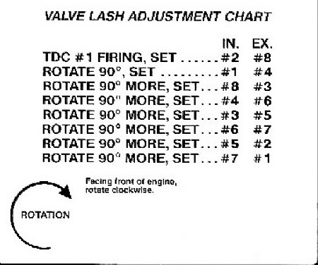
Also we are setting or trying to the valves(solid lifters) on it. I noticed that the rocker arms dont sit totally flat on the valve stems, so when checking the clearance( .021 for exhaust and .013 for intake) do you slide the feeler gauge from the side(parallel to the rocker arm) Or do you slide it in from front to back on the engine?? Also when turning the adjusting screw, should we hold the rocker arm so that it keeps pressure on the pushrod??I know these might be stupid questions, but just trying to be as accurate as possible?? By the way we are setting with feeler gauges, no access to dial indicator.

Thanks again for all your help!
 
Only way I know of to check the balancer, AND ONE OF THEM MAY have slipped whether correct balancer or not, is to use a piston stop. Easy.

Biggest thing with adjusting valves is you want to be sure you are on the backside of the cam. There is a chart for this:

Valvelashadj.jpg


But I just use the EOIC method. This means that

When the EXHAUST is starting to OPEN you adjust the intake on that cylinder

When the INTAKE is nearly CLOSED you adjust the exhaust for that cylinder

Make sure the feeler is parallel to the top of the valve stem, you can "feel" this by wiggling it. I usually use the feeler "I want" for clearance and another that is .002-3 larger. I adjust so the one I want goes, the larger does not.
 
Sounds like one balancer is for an early motor with the timing marks on the passenger side of the timing cover, and the other is for a later motor with the timing marks on the drivers side of the timing cover. You will have to put the motor at TDC #1 compression and see which balancer lines up with your timing cover.
 
Ok, refresh my memory here, but I thought TDC for #1 (compression)you can set both intake and exhaust for #1?? Then rotate crank 90* and set #8 (intake and exhaust), turn another 90* then set 4 intake and exhaust?? The chart above looks different?? Also when you say backside of the cam, you mean on the downside of the cam lobe correct??
 
If you set it according to the chart you will be okay. This eliminates the factor of overlap in timing. Anything else is just a guess. I'm not saying it won't work w/ other methods, but it beats fining out the hard way.
It really doesn't matter which way you insert the feeler gauge as long as it's positioned between the rocker arm & the valve tip evenly. The amount of drag is more critical since too tight or too loose will not give you the proper clearance. I would suggest practice by getting a feel for the correct amount of drag on the gauge by putting the gauge in the jaw of a micrometer adjusted to the gap or lash amount you want & pulling the feeler gauge through it to get the feel for it. In other words set your micrometer to .021" & pull the feeler .021" gauge through it. Same thing for the .013" gauge, mic set @ .013". You shouldn't need to hold the rocker in place because once the lash is set w/ the feeler gauge in it there should be no clearance until you remove the feeler gauge.
 
Ok, refresh my memory here, but I thought TDC for #1 (compression)you can set both intake and exhaust for #1?? Then rotate crank 90* and set #8 (intake and exhaust), turn another 90* then set 4 intake and exhaust?? The chart above looks different?? Also when you say backside of the cam, you mean on the downside of the cam lobe correct??

No, don't set valves with the cylinder you are seting at TDC. The valves are not at maximum clearance (are not on the back of the cam) at TDC. That is the reason for the chart, and the EOIC ditty
 
Sounds like one balancer is for an early motor with the timing marks on the passenger side of the timing cover, and the other is for a later motor with the timing marks on the drivers side of the timing cover. You will have to put the motor at TDC #1 compression and see which balancer lines up with your timing cover.

Steve...you have to use the late balancer with the late timing cover, and early with the early, otherwise your timing light (and TDC) indication will be way off.
 
When adjusting the rockers, you either just muscle the OEM no lock interference fit adjusters, or back of an adjusting screw, adjust and then hold with allen wrench and tighten the lock nut. The marks are not exactly 90 off, but are pretty close, If you are marking a new/different damper, you need to use a piston stop and a degree wheel. turn piston till it hits stop, mark on degree wheel, turn the other way until it hits the stop and mark. bisect the degrees and paint new mark on damper with liqued paper, nice and bright.
 
At dads right now and am frustrated to sh*t!! We have tried setting the valves with the chart....twice and then tried the EOIC method, with the eoic method, we couldnt get past #1 cylinder, (wont turn over)I looked in the xhaust port and it looks like the valve wants to hit the piston???? If we use the chart, we get as far as setting 2,8, then 1,4 then wont turn over???
 
Talked to Steve this morn. on the landline. Sounds like he has a valve geometry / binding problem "had to change the adjustment A LOT from the old cam"

He went from a solid lifter cam to a solid lifter cam, so QUESTION:

Are some aftermarket lifters different installed height from OEM? I know hydraulic and solid used to use different pushrods.
 
Yes some companies have different heights I have three solid lifters here for mopar and all three are different
 
Ditto on the small block balancer. It is ~90 deg difference between early and late crank dampener marks, but I don't know if exactly 90 deg. Early ones are with a cast-iron water pump (64-69?) and later are with the aluminum water pump (70+). I don't know that the dampeners interchange. I read somewhere that later ones are thicker, and some after-market ones are thicker still, so that could throw off pulley grooves. May also be balancing issues. Since I changed to the alum water pump in my 65, and later timing cover, I just cut a new timing mark in my original dampener.

Good info about where to set the crank when adjusting valves. I always set the piston at TDC and ASSumed the cam would be on the base circle there. Now I find not always true. I put a hydraulic cam in my 65 SB (w/ adj. rockers), so no concern since that is just for the pre-load set. My Mercedes diesels are ohd cam, so I just put the lobes opposite the lifters. Strange that different solid lifters would be different heights. Is that measured from where the push-rod sits?

Check on the slant six forum. Those are also solid lifters, and many slanters adjust the gaps with the engine running. I wonder if similar could be done with a 273, but maybe they sling more oil.
 
At home now on break, so dad is gonna pull the new lifter and compare with the old ones. Oh with the red balancer, which is the one we have been using, we turned the engine over until you could feel compression on #1 cyl, looked at the groove in the balancer and it matched up with 0 on the timing marker. So Im assuming good??
 
i dont know if this helps Steve, but when you get back to adjusting the valve lash, with my 6 i always did it with the engine running. it was so much easier because there is little room for error. i have never done a 273
 
At home now on break, so dad is gonna pull the new lifter and compare with the old ones. Oh with the red balancer, which is the one we have been using, we turned the engine over until you could feel compression on #1 cyl, looked at the groove in the balancer and it matched up with 0 on the timing marker. So Im assuming good??

If you're just starting to "feel" compression and it's already hitting 0 on th etiming mark you might still be off. Pull the spark plugs and find out where TDC really really is, it's not that hard, just stuff a screwdriver (or rubber coated plier handle or a fancy non-marring plastic depthfinder or whatever) - make sure you hold it at the exact same depth - into the sparkplug hole, turn clockwise until you tap, mark it, then rotate counterclockwise until it taps again, mark it there. Put a measuring tape on the balancer to measure the distance between the marks, divide it in half, and mark that. That's real TDC and it will take you ten minutes to find. If the balancer is marked right? Great, now at least you know. It doesn't sound like you're a total chucklehead, so I am willing to say isn't installer error, but proving that requires knowing you're at TDC. TBH if the lifters are OK and you're adjusting from true TDC, this whole thing kinda reeks of misground/mislabeled cam, it's not super duper common but it _does_ happen, I've not had one myself.
 
If you're just starting to "feel" compression and it's already hitting 0 on th etiming mark you might still be off. Pull the spark plugs and find out where TDC really really is, it's not that hard, just stuff a screwdriver...................

NOT a very accurate method. The accepted method with the heads on is to use a piston stop, and you can easily make one from an old plug---or buy one, like this:

http://www.jerrybramlett.net/images/pic_installation.jpg

Remove no1 plug, make sure the piston is "down some" and remove the battery ground. You may have to play with the length the first time around.

Wrench the engine around until it stops on the device, make a mark on the balancer directly under 0 (TDC) on the timing tab. Repeat going counter clockwise.

Now you'll have two marks some distance apart. TRUE TDC will be halfway in between, and if the marks are accurate, that is where it will be.

You can get some idea if you 'effed up on the cam by referring to the timing card for the cam, IE intake opens so many degrees, etc. and all you need to do for that is check one or two points TO GET SOME IDEA if you really messed up

Measure the balancer around the outside carefully, with a small flexible tape. Calculate how many "degrees per inch" on the balancer, and measure around from TDC to get your reference point.

Another trick, which is no longer true on most cams, but will at least give you SOME idea if the cam is close, is the old method known as "split overlap"

What this means is, you bring no6 up ready to fire (both valves closed) on the timing mark, zero or TDC. At this point, on SOME cams, both valves for no1 will be "equally open" IE one is opening, the other is closing, but they are both open. One more time, "modern" cam timing has pretty much thrown this out the window, but it WILL give you a "dirty" checkpoint.


After talking to Steve on the phone, it sure sounds like valve train geometry, IE lifters different height.
 
67dart273, thank you for taking the time today to call me, sorry it was a quick conversation...barely made it to work in time.

Well just got off the phone with dad, he pulled a lifter and compared it with the old ones...same height. I told him to put a push rod in an old one and a new one and chk that height...both the same height....so Im planning on going in to dads early and chk where and how the pushrods make contact with the rocker arm and the lifter....I dunno what else to chk. Here is the link to the cam specs http://www.compcams.com/Company/CC/cam-specs/Details.aspx?csid=665&sb=2
 
Oh, when we installed the dbl roller and chain, we made sure the dot on the cam gear was at 6 oclock and the dot on the crank gear was at 12..sounds right??
 
What all in detail have you changed? Using the same valves? Same rockers? push rods?

You mentioned you had to change the valve adjusters "a long ways." If that is so, there HAS to be something in there that has changed.
 
67Dart is doing a good job here so I won't mess things up with a different point of view. Don't feel like the Lone Ranger. I had similar problems when I rebuilt mine. With the right length of pushrods and shimming the rocker shafts, I was able to get close to the proper rocker arm geometry and lash. Photo is from post #70 on page 3 of my engine build thread. toolmanmike
 

Attachments

  • engine 173.jpg
    71.1 KB · Views: 560
-
Back
Top