A month ago I was driving and some white acrid came through the firewall. Thinking I had an engine fire I pulled over to check it out - nothing. A short time later the alternator failed, which I replaced. However it is still not charging the battery. I replaced the regulator, started the car and more acrid white smoke. This time the car was stationary and the smoke clearly came from the area of the regulator. Any ideas why it's eating regulators and how to fix it?
You are using an out of date browser. It may not display this or other websites correctly.
You should upgrade or use an alternative browser.
You should upgrade or use an alternative browser.
Charging problems 67 Barracuda
- Thread starter brodphish
- Start date
-
68gtxman
I used to reMember
Bad ground connection? Or could be too high a load on the electrical circuit - from a big stereo system? Could also be a bad bulkhead connector at the firewall. Pull it apart and inspect it.
Great I will check both. They both sound like simple fixes which are my specialty. Thanks.
Very first thing I'd check is the green field wire going from the VR to the alternator field. Might be shorted. These systems are incredibly easy to check out
Basic diagram:

And by the way that diagram came from MyMopar. If you need a service manual you can download one there free
Basically the VR must be grounded
On the old systems, one of the brushes is internally grounded
So ignition voltage feeds TO the VR, this is the same circuit feeding the coil ballast. Through the VR and out on the green field wire to the alternator.
======================================================
Take an alligator clip lead and unhook the green wire at the alternator. Clip your alligator to the exposed alternator field terminal, and run it over to battery, IE the starter relay big stud
Start and run, bring up RPM. Ammeter should show a charge
Check out the green field wire for shorts and continuity.
Basic diagram:
And by the way that diagram came from MyMopar. If you need a service manual you can download one there free
Basically the VR must be grounded
On the old systems, one of the brushes is internally grounded
So ignition voltage feeds TO the VR, this is the same circuit feeding the coil ballast. Through the VR and out on the green field wire to the alternator.
======================================================
Take an alligator clip lead and unhook the green wire at the alternator. Clip your alligator to the exposed alternator field terminal, and run it over to battery, IE the starter relay big stud
Start and run, bring up RPM. Ammeter should show a charge
Check out the green field wire for shorts and continuity.
momoparman
MOISMYHOME
Most times they are fire wall ground problems. Try running a permanent dedicated ground from the battery to the bolt that holds the VR to the firewall. Use a ring terminals on both ends. Good way to guarantee that you will always have a good ground ref.
The smoke is usually the VR toasting during overload. The alternator overcharges the battery as well so that should be looked at. You will see leaking around the sealed caps if you have OL'd the battery. You should have both alt and battery checked before you try one more VR.
This is a very common problem as the car get older and the connection between the VR case and the firewall become oxidized/corroded.
Good luck.
If possible post a photo of your new alternator. There is a lot of "malfeasance" going on with replacements. Some have two field connections, one of which is grounded. This means it's "too easy" to mistakenly connect the green wire to what amounts to a grounded connection.
Check the field resistance with your ohmeter.
Check the field resistance with your ohmeter.
The old alternator had a clip style connector on the green wire. The new alternator had a bolt so I used a circle terminal to run to a male clip end, which I attached to the original female on the green wire. I think I got good connections everywhere.
Attachments
OK now WAIT a minute. Your car should have ONE field connection...........the green wire to field, and the other field brush should be GROUND
That photo?? appears that the green wire IS grounded which you do NOT want
What is hooked to "1" and what is hooked to "2"
And.........what does your VR look like
That photo?? appears that the green wire IS grounded which you do NOT want
What is hooked to "1" and what is hooked to "2"
And.........what does your VR look like
Attachments
So the two black wires on either side of the alternator are both the same color (black) and gauge. The one on the left in the pictures runs to a ground on the firewall. The one on the right (attached by the nut) appears to run to a sliver box just below the VR. The black square is the VR and the last picture is the silver box the alternator lead runs to.
The old alternator was hooked up just like the pictures I attached, including the green wire hooked up in the center. Although there was a different style connection to the alternator, as I mentioned. A clip instead of a set screw / bolt.
If I switched the left black and green wires would that solve the problem? Or take off the left black and put the green there? Just guessing.
Attachments
67notch
Active Member
Sorry I don't have anything to add to the thread, but I've seen pictures of your car on the internet before. I love the shaker hood! I want to do that to my 67. Did you do the fabrication on the hood or did someone else?
So the two black wires on either side of the alternator are both the same color (black) and gauge. The one on the left in the pictures runs to a ground on the firewall. The one on the right (attached by the nut) appears to run to a sliver box just below the VR. The black square is the VR and the last picture is the silver box the alternator lead runs to.
The old alternator was hooked up just like the pictures I attached, including the green wire hooked up in the center. Although there was a different style connection to the alternator, as I mentioned. A clip instead of a set screw / bolt.
If I switched the left black and green wires would that solve the problem? Or take off the left black and put the green there? Just guessing.
Here's the thing? Impossible for me to really tell from the photos. Don't overthink this. The "difference" is that....
up through 69, one field brush was forcibly grounded, that is, you could not UNground it. This left only one wire to connect and run over to the VR
Starting in 70 BOTH brushes were insulated and had terminals, because the VR was different. You can USE a later alternator by grounding one or the other of those terminals and hooking your VR (green) wire to the remaining brush
But what MIGHT be happening here is you might be grounding the green wire. I simply cannot tell from the photos.
Below is what your original alternator (when car was built) should look like. The hardware at 3 o'clock marked GRD is the grounded brush. Click the link
http://i282.photobucket.com/albums/kk273/AAR-Cuda340/Cars-Trucks/Alternator4.jpg
There are variations, not all of them "factory."
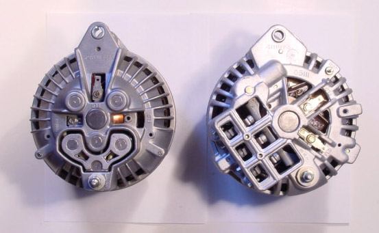
Below is a "hack" created by a "hack" of a so called rebuild shop. This has been a lot, way too much, and the thems that did it should be hung by the parts. What you see here is an original 69 alternator that has been drilled to accept an isolated brush to "convert" it into a 70 / later unit. The problem is, sometimes these mistakenly ALSO came with a grounded brush. This can cause problems!!
The factory isolated brush is at 9 oclock, the factory grounded brush is at 6 oclock, WHICH IS INSTALLED, and the "hack" brush which is missing is at 12 o'clock
Below is a 70 or early 70's 'isolated field' alternator. This is still the older "roundback" design, but the grounded brush is gone, and has two isolated brushes. You can use these on the older system by grounding EITHER brush and hooking the remaining brush to the VR. THIS APPEARS to be what you have, whether it's correctly connected is another matter

Below we have yet two more variations. On the left is a round back which I have never seen. This has a version of the "hack" isolated brush, except it is commercially done. This might be an aftermarket casting, I don't know. Again, this one has a grounded brush installed, and the empty hole is for an isolated brush.
On the right is the later model isolated unit. These have two isolated brushes, and are a better design. you can also use these by grounding either brush, and connecting the remaining to the VR
On the right is the later model isolated unit. These have two isolated brushes, and are a better design. you can also use these by grounding either brush, and connecting the remaining to the VR
Mercy....
I'm not understanding the text or the pics. Voltage regulator is cased in black plastic ? I see blue in and green out which would be correct configuration for your car but how the heck is plastic regulator grounded ?
Other pic shows the ballast resistor. That is the 'silver box" you mentioned ? An extra wire ( wrapped with tape ) is attached with/where blue and brown attach ? And it goes to where ?
BillGrissom
Well-Known Member
The black plastic box is something custom. Unless you know why, I would re-wire it more standard. You probably smoked your VR by grounding the grn wire, so buy a new electronic type (~$11 rockauto). Some look like the original ugly black box and some are thinner chrome. Connect the green wire to its "fld" terminal and to a terminal on your alternator which is not grounded (check w/ an ohmmeter). The other alternator terminal should be grounded, which you can do with the existing black wire.
67Notch - I bought the car "as is" but I know a little about the shaker hood. TEH car actually has a 69 hood and grill assembly - if you look closely in the pic you can see nose ridge. They did this as the 69 hood has bracing underneath that made for a much more rigid structure. As it is they cut 3 hoods to get it right. Images of this car often come up first with a search under 67 Barracuda, which I found out AFTER I bought the car. Oh well only fellow Mopar nuts are looking anyway.
So there are a lot of possible permutations of what's wrong. BillGrissom seems like it would be the easiest fix for me although it's obvious 67dart273 has a wealth of knowledge on what may be wrong. I am not a good mechanic but getting better. Can someone explain how to use an ohmmeter to differentiate between a field terminal and a ground terminal?
Thanks to all who took the time to help me.
Sure, post up your meter brand and model, so we can help you get it "set" correctly.
The thing is you need to be careful and deliberate measuring a low resistance, because you are trying to decide between "zero" and "only a little bit" that is only a few ohms. I don't recall exactly what field resistance is, maybe, 2--4 ohms or so. If either of them is grounded, the reading should be nearly zero
This is complicated by bad connections at the probes, corrosion at the connection, and what is called "lead resistance" that is resistance in the test leads of the meter. Some meters (fluke) have a function that "zeros out" the test leads.
You probably should either remove the alternator, or at least swing it out on the adjuster and try to get a better photo, maybe we can tell by looking
I have a GB Instruments GMT-18A multi-function instrument. It's more of a household item but it's worked on the limited automotive applications for which I've used it. Seems to work OK.
67dart I just looked the link you sent earlier. That is exactly how the old alternator looked. THE new on is a little different. I am going to check the brush marks on the new one and off to work.
BillGrissom
Well-Known Member
To add, most multimeters (like free w/ coupon Harbor Freight one) don't have a "zero ohms" function, but still work fine. Just touch the leads together and note the "zero reading" and subtract it from subsequent ohm readings. I also don't recall the resistance of the "field windings" (between 2 terminals/brushes). I would guess the field draws <1 A, so probably 12 ohm or higher.
I does get tricky trying to measure <2 ohm accurately, such as trying to measure ground resistance. Often, for a large current like alternator output or starter draw, it is more telling to measure the voltage drop from the case to BATT- as the device is drawing current. In general, you want to see <1 V drop back to BATT- from all grounded cases (alt, Vreg, starter, engine block). I once saw the speedometer cable in my M-B smoking as I cranked the engine, an obvious sign of a corroded engine ground connector. A new alternator I installed in my 69 Dart didn't output current until I clipped a jumper cable from its case to BATT-, another sign of a bad return path (alt to block). Both were problems with oxidized aluminum that a little sanding fixed.
I does get tricky trying to measure <2 ohm accurately, such as trying to measure ground resistance. Often, for a large current like alternator output or starter draw, it is more telling to measure the voltage drop from the case to BATT- as the device is drawing current. In general, you want to see <1 V drop back to BATT- from all grounded cases (alt, Vreg, starter, engine block). I once saw the speedometer cable in my M-B smoking as I cranked the engine, an obvious sign of a corroded engine ground connector. A new alternator I installed in my 69 Dart didn't output current until I clipped a jumper cable from its case to BATT-, another sign of a bad return path (alt to block). Both were problems with oxidized aluminum that a little sanding fixed.
I have a GB Instruments GMT-18A multi-function instrument. It's more of a household item but it's worked on the limited automotive applications for which I've used it. Seems to work OK.
OK, simple, old school meter. Simply set the selector to OHMS X1 down at far right (not X1K), and hold the probes VERY tightly together. Carefully set the red knob to "0" ohms. In the Navy, our meters were supposed to be calibrated (we were told) lying flat on their back. Maintain the same position you zero the meter in. Be careful of meter face static, which can throw things off. Often, "fogging" the meter with your breath will drain it off
You are only looking for a difference of a couple of meter scale marks between 0 and whatever the field might be so be careful with the reading

SO I checked the brush marking on the new alternator and guess what - even though it looks like virtually identical to the old one the field / ground brushes are reversed on the new. They are faint but there and frankly I did not know to look for them. Just hooked it up the same way. So maybe all I have to do is switch the green wire clip to the 9 o'clock "FLD" and the black to the 6 o'clock clip. Insatll a new VR and I should be good.
The car has a 340 punched to 417. O'Reilly's Auto parts shows a 35/46 AMp VR and a 60 Amp VR. Which is the correct one to install? The first replacement they did not give me a choice.
This should be my last question! Hopefully by Friday I can report back it's all good. Thank you for all the advice!!!
67dart I can't believe I missed the link first time through. Although reading and re-reading I was better able to pick up on it when I did open the link.
OK before you connect the new VR, try this: When you "believe" you have the alternator hooked up right, (the green) take the OTHER end of that green and "clip" it to the battery with a jumper. You should see a small spark in subdued light. Very small. Now start and run the engine and bring up RPM. Charge should increase dramatically. Unhook your jumper and recheck. Should not charge.
This might save you from eating another VR Make certain the VR is grounded
This might save you from eating another VR Make certain the VR is grounded
-
Similar threads
- Replies
- 54
- Views
- 3K
- Replies
- 4
- Views
- 452
- Replies
- 25
- Views
- 1K
- Replies
- 11
- Views
- 692


